Table of Contents
Advertisement
Advertisement
Chapters
Table of Contents

Related Manuals for Sherwood R-977


Summary of Contents for Sherwood R-977
-
Page 2: Safety Precautions
Safety Precautions READ THIS BEFORE OPERATING YOUR UNIT This symbol is intended to alert the user to the presence of uninsulated “dangerous voltage” within the product’s enclosure that may be of sufficient magnitude to constitute a risk of electric shock to persons. CAUTION TO REDUCE THE RISK OF ELECTRIC SHOCK, DO NOT REMOVE COVER... - Page 3 According to Electronic Information Products Pollution Control Measures for the Administration of toxic and hazardous substances or elements of the identification table Toxic and hazardous substances or elements Remarks Parts Name Object parts Cr6+ PBDE Circuit board assembly, installation, Board insert the components, circuit board (not including certain electronic components) Top cover, bottom cover, the bottom shell,...
-
Page 4: Table Of Contents
Contents Connecting Bluetooth connector Safety Precautions Contents OPERATIONS PREPARATIONS Powering on the System Listening to a Program Source Checking What’s in the Box Enjoying Surround Sound Flow of Connecting and Settings Surround modes Controls and Displays Selecting the surround mode Front panel Cancelling the surround mode for stereo Fluorescent display... - Page 5 HDMI Assign Using a punch-through function Component Assign Removing a punch-through function Digital Audio Assign Connecting PC for Upgrades Video Mode Updating the R-977 Audio Mode Troubleshooting Guide Video Scaling Specifications AV Sync Setup Code Table DC Trigger1 & DC Trigger2...
-
Page 6: Preparations
Universal remote Room 2 remote Batteries AC input cord (Receiver) control control O E A NG N T U T O S R-977 NETWORK AV RECEI ER Setup MIC FM wire antenna AM loop Antenna Isolator WiFi antenna Operating antenna... -
Page 7: Controls And Displays
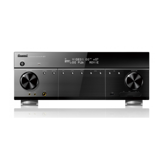
Preparations Controls and Displays Front panel 13 14 Go to Go to Name Name page(s) page(s) SURROUND mode UP()/ POWER ON/STANDBY button DOWN() buttons INPUT SELECTOR knob MASTER VOLUME control knob PURE AUDIO indicator SETUP MIC jack MONITOR SELECT button FRONT AUX jack Remote control sensor HEADPHONE jack... -
Page 8: Fluorescent Display
Preparations Fluorescent display 13 14 Go to Go to Indicator Indicator page(s) page(s) SPEAKER indicators MUTE indicator • HL : Front Height Left speaker MEMORY (station) indicator • HR : Front Height Right speaker Room 2 indicator • : Speaker Room 3 indicator •... -
Page 9: Rear Panel
Preparations Rear panel Go to Go to Name Name page(s) page(s) COMPONENT IN jacks DIGITAL OUT (OPT.) connector COMPONENT OUT jacks DIGITAL IN (OPT. & COAX.) connector ROOM 2 SPEAKER connectors IR IN/OUT jacks DC TRIGGER OUT jacks WiFi ANTENNA connector AUDIO IN jacks LAN/ETHERNET connector FM/AM ANTENNA terminals... -
Page 10: Universal Remote Control
Preparations Universal remote control Button(s) POWER ON button STANDBY button DEVICE buttons MACRO buttons SLEEP timer button/AUTO STANDBY timer button ROOM 2 INPUT SELECTOR button ROOM 2 VOLUME UP(+)/DOWN(−) buttons ROOM 2 ON/OFF button MUTE button CHANNEL LEVEL button VOLUME UP(+)/DOWN(−) buttons TUNING UP(+)/DOWN(−) buttons PRESET UP(+)/DOWN(−) buttons SKIP AHEAD(... -
Page 11: Inserting The Batteries
Preparations Inserting the batteries Remove the cover. Insert two AAA size 1.5v alkaline batteries matching the polarity. Caution • Remove the batteries when they are not used for a long time. • Always use alkaline batteries, and do not use the rechargeable batteries (Ni-Cd type). •... -
Page 12: Room 2 Remote Control
Preparations Room 2 remote control Button(s) POWER ON button POWER OFF button INPUT SELECTOR buttons TREBLE UP( )/DOWN( ) buttons BASS UP( )/DOWN( ) buttons PRESET UP(+)/DOWN(−) buttons VOLUME UP( )/DOWN() buttons MUTE button Inserting the battery Release the battery tray. Insert the CR2025 battery matching the polarity. -
Page 13: System Connections
System Connections You can use a variety of video/audio equipment with this receiver for both playback and recording. Connecting Antennas To listen to radio stations, connect the AM loop antenna and the FM wire antenna as illustrated below. FM antenna Indoor Antenna Outdoor Antenna Connect the FM indoor antenna to the FM... -
Page 14: Connecting Video Components
System Connections Connecting Video Components Connect the cables to be used. Carefully check the left (L) and right (R) channels and the inputs and outputs, and be sure to interconnect correctly. Connecting a BD/BDR BD/BDR OPT. (COMPOSITE) AUDIO AUDIO COMPONENT OPT. -
Page 15: Connecting A Dvd/Dvr
System Connections Connecting a DVD/DVR DVD/DVR OPT. (COMPOSITE) AUDIO COMPONENT OPT. HDMI VIDEO • Select one of the video connectors (HDMI IN, COMPONENT IN, or VIDEO IN) and one of the audio connectors (HDMI IN, COMPONENT IN, or AUDIO IN), and connect the cables. •... -
Page 16: Connecting A Stb/Cbl
System Connections Connecting a STB/CBL STB/CBL (COMPOSITE) AUDIO HDMI VIDEO • Select either the HDMI IN (digital) or VIDEO & AUDIO IN (analog) connectors, and connect the cables. • For connecting MONITOR (TV, projector, etc.), see “Connecting a monitor” on page 17. •... -
Page 17: Connecting A Monitor
System Connections Connecting a monitor Select one Monitor (TV, projector, etc.) (COMPOSITE) COMPONENT HDMI VIDEO • When you make a digital connection, you can select one of the HDMI MONITOR OUTs depending on your situation. Otherwise, you can select either COMPONENT OUT or (COMPOSITE) VIDEO OUT for analog connection. -
Page 18: Connecting Audio Components
System Connections Note (Continued) • The audio signals from the HDMI connector (including the sampling frequency and bit length) may be limited by the component that is connected. • The video signals will not be output properly if the connected component is incompatible with HDCP. •... -
Page 19: Connecting A Cdp/Phono
System Connections Connecting a CDP/PHONO Turntable with MM type cartridge COAX. AUDIO • Select one of the audio connectors (COAX. IN or AUDIO IN), and connect the cables. • If you connect the DIGITAL INs to your components, it is easier to do so by following the default settings: OPT. IN 1 : BD/BDR, OPT. -
Page 20: Connecting Preouts
System Connections Connecting PREOUTs Use these jacks when adding additional power amplifiers. Power amplifier Front speakers FRONT CENTER Center speaker Surround speakers SURROUND Powered subwoofer 1 Powered subwoofer 2 Surround back speakers SURROUND BACK • Connect the PREOUT jacks to the powered speakers or the power amplifiers connected to speakers respectively. -
Page 21: Connecting Speakers
System Connections Connecting Speakers Carefully check the left (L) and right (R) channels and the polarities on the speakers being connected to this receiver. FRONT FRONT CENTER SURROUND SURROUND SURROUND BACK SURROUND BACK FRONT HEIGHT FRONT HEIGHT right left right left right left... - Page 22 System Connections • Be sure to connect speakers firmly and correctly according to the channel (left and right) and the polarity (+ and −). If the connections are incorrect, no sound will be heard from the speakers, and if the polarity of the speaker connection is incorrect, the sound will be unnatural and lack bass.
-
Page 23: Speaker Placement
System Connections Speaker placement Ideal speaker placement varies depending on the size of your room and the wall coverings, etc. The typical example of speaker placement and recommendations are as follows: Front left and right speakers and center speaker ... -
Page 24: Connecting Room 2 & Room 3 Outs
System Connections Connecting ROOM 2 & ROOM 3 OUTs In addition to the main room, you can enjoy playback in up to two other rooms (ROOM 2 and ROOM 3). Use high quality connection cords to minimize hum or noise. Connecting ROOM 2 OUTs Connecting ROOM 2 OUTs to the components Main room... -
Page 25: Connecting Multi-Room System Kit
System Connections Connecting Multi-room System Kit You can control this receiver or other compatible components from another room with the remote control after installing the Multi-room system kit. Connect the IR IN jack to the output of the connecting block of the multi-room system kit to control this receiver from Room 2 with the remote control. -
Page 26: Connecting Dc Trigger Out
System Connections Connecting DC Trigger Out [ Wireless LAN ] Connect a component to one of the DC TRIGGER Internet OUT jacks that allows DC 12V to turn on when a specific input source is selected. For details, refer Router with access point Modem to the operating instructions of the components to... -
Page 27: Using Front Panel Connectors
BD player, a DVD player, etc. Connecting Bluetooth connector If the Bluetooth IN connector is connected to Sherwood Audio Receiver BT-R7 with Bluetooth F HDMI wireless technology, you can enjoy music wirelessly with a music player featuring Bluetooth wireless technology such as MP3 player, mobile phone, etc.. -
Page 28: Operations
Operations Before operating this receiver, first set the unit as desired for optimum performance by setting the Setup menu. Powering on the System Listening to a Program Source Press ON/STANDBY button on the front panel or Turn the INPUT SELECTOR knob on the front POWER ON button on the remote control. -
Page 29: Enjoying Surround Sound
Operations Enjoying Surround Sound DTS-HD Master Audio Designed to take full advantage of the additional This receiver incorporates a sophisticated Digital storage space offered by the new Blu-ray and HD Signal Processor that allows you to create optimum DVD disc formats, this new DTS format offers up sound quality and sound atmosphere in your personal to 7.1 discrete channels of uncompressed digital Home Theater. - Page 30 Operations Dolby Pro Logic IIx Hall This mode expands any 2-channel source for This mode provides the ambience of a concert hall for 7.1-channel playback. It provides a very natural and classical music sources such as orchestral, chamber seamless surround sound experience that fully music or an instrumental solo.
-
Page 31: Selecting The Surround Mode
Operations Selecting the surround mode Before surround playback, first perform the speaker setup procedure, etc. on the OSD settings for optimum performance. For details, see “Setting the Speaker/Room EQ Setup” on page 57. Select the desired surround mode by pressing the SURROUND UP(>)/DOWN(<) buttons. -
Page 32: Cancelling The Surround Mode For Stereo Operation
Operations Cancelling the surround mode for • When the speaker setting is “NO”, the test tone of the corresponding channel is not stereo operation available. Press the STEREO button. • TEST SETUP Depending on the signal format which is being D SC MENU HOME MENU input, either the stereo mode or the 2CH... -
Page 33: Adjusting The Current Channel Level
Operations Adjusting the current channel level Note • Depending on the speaker settings (“NO”, etc.) After adjusting each channel level with test tone, and surround mode, etc., some channels cannot be adjust the channel levels according to the program selected. sources or to suit your tastes. -
Page 34: Memorizing The Adjusted Channel Levels
Operations Memorizing the adjusted channel levels Recalling the memorized channel levels You can memorize the adjusted channel levels into Press the CHANNEL LEVEL button. preset memory (“REF1” or “REF2”) and recall the memorized channel levels whenever you want. • “CAL” (or “REF1”, etc.) is displayed on the fluorescent display for several seconds. -
Page 35: Listening To Radio Broadcasts
Operations Listening to Radio Broadcasts Auto tuning Press the BAND button on the front panel or Selecting the band TUNER button on the remote control to select the desired band. Press the BAND button on the front panel or Press the TUNING UP(+)/DOWN(−) buttons for TUNER button on the remote control to select the more than 0.5 second. -
Page 36: Auto Presetting
Operations Auto presetting Manual presetting Select FM by pressing the BAND button on the Tune in the desired station with auto or manual front panel or the TUNER button on the remote tuning. control. Press the ENTER button. • Auto presetting function is available for FM stations only. -
Page 37: Tuning To Preset Stations
Operations RDS Tuner (Regional Option for Press the ENTER button again to confirm your selection. some countries in Europe, etc.) • The station has now been stored in the memory. • A stored frequency is erased from the memory LISTENING TO RDS BROADCASTS(FM ONLY) by storing another frequency in its place. -
Page 38: Tp Search
Operations While displaying "RDS SRCH". While displaying "TP SRCH". • The tuner automatically searches stations • The tuner automatically searches stations offering RDS services and the station name is broadcasting the traffic program. displayed. • "NO TRAFFIC" is displayed if the signal is too •... -
Page 39: Displaying Rds Information
Operations Displaying RDS information While displaying "PTY SRCH", select the desired program type. In the FM mode, • Each time these buttons are pressed, one of 29 different types of programs is selected. (NEWS, AFFAIRS, INFO, SPORT, EDUCATE, TEST SETUP DRAMA, CULTURE, SCIENCE, VARIED, POP DISC MENU HOME MENU... -
Page 40: Listening To Internet Radio Stations & Music Files
Operations Listening to Internet Radio USB memory devices A USB memory device can be connected to the Stations & Music Files USB connector on the front panel to play music files stored on it. You can listen to Internet radio broadcasts or music Only USB memory devices conforming to mass files stored on a USB memory device or a computer ... -
Page 41: Net/Usb Menu
Operations Compatible audio file formats For Internet radio, USB memory device and media server playback, this receiver supports the following music file formats. File format Sampling frequency Bit rate Extension 32/44.1/48 kHz 32~320 kbps .mp3, .MP3 32/44.1/48 kHz 32~320 kbps .wma, .WMA 32/44.1/48 kHz 32~320 kbps... -
Page 42: Basic Operation
Operations Basic operation Press the ENTER button to confirm your selection. Make the necessary preparations. • Check the network environment, and then turn TEST SETUP on this receiver. For details, see “Connecting to DISC MENU HOME MENU Network” on page 26. ENTER •... - Page 43 Operations To pause playback To play repeatedly During playback, press the PAUSE( ) button. During playback of the desired music files, press the REPEAT( ) button. • The playback will be stopped at the point where the button is pressed. DISPLAY DIMMER •...
-
Page 44: Now Playing
Operations Now Playing Internet Radio You can listen to Internet radio broadcasts provided You can display the information of the Internet by vTuner. radio broadcast or music file being played through the fluorescent display and/or the monitor TV Select the desired category (or item) by pressing connected. -
Page 45: Music Servers
Operations Music Servers Music Streaming by Smartphone Smartphone's Music file can be played at R-977 by You can listen to music files stored on a computer using Music Play Application(supported DLNA) on Wi- (media server) connected to this receiver via a wired/ Fi or wireless network. -
Page 46: Ipod
Operations Recording iPod You can listen to music files stored on your iPod. The digital signals from the coaxial, optical digital input or HDMI IN can be heard but cannot be Connect iPod to the USB connector through the recorded. usb cable, and then turn the iPod. -
Page 47: Dubbing From The Audio And Video Signals
Operations Dubbing from the audio and video signals Digital audio recording with MD separately onto VIDEO 1 (BD/BDR) recorder When the OPTICAL DIGITAL OUT of this receiver Example: when dubbing the VIDEO 3 (STB/CBL) is connected to the OPTICAL DIGITAL IN of the video signal and the CD audio signal separately recorder, you can enjoy high-quality sound of digital onto VIDEO 1 (BD/BDR) -
Page 48: Using Other Functions During Playback
Operations Using Other Functions during Setting the SLEEP timer Playback Press the SLEEP button. • SLEEP timer indicator ( ) lights up. • Each time the button is pressed, the sleep time Listening with headphones changes as follows: OFF 90min 60min 30min Connect the headphones to the PHONES jack on the front panel. -
Page 49: Achieving Higher Purity Of Sound Quality
Operations Achieving higher purity of sound quality Adjusting the brightness of the fluorescent display Press the PURE AUDIO button. • The PURE AUDIO indicator lights up, the Press the DIMMER button. fluorescent display goes off and all the video- • Each time the buttons is pressed, the display related circuits are turned off, meaning no video mode changes as follows:... -
Page 50: Confirming The Hdmi Function
Operations Multi-room operation Confirming the HDMI function To use the HDMI control functions properly, it is In addition to your main room, you can also enjoy recommended to confirm the HDMI control functions playback in two other rooms (ROOM 2 and ROOM 3). usable with each connected component by performing the following operations. -
Page 51: Listening To Room 3 Source
Operations Listening to ROOM 3 source Adjust the ROOM 2 volume by pressing the ROOM 2 VOLUME UP(+)/DOWN(−) buttons. You can select different sources for main room • The MUTE button on the ROOM 2 remote or ROOM 2 and play them at the same time. The control can be available only when the ROOM 2 ROOM 3 function is only controlled by the OSD menu function is operating. -
Page 52: Osd Menu Settings
OSD Menu Settings The setup menu displayed on the monitor TV allows you to perform the setup procedures easily. Overview The OSD (On-screen Display) menu is a setting menu that is displayed on the monitor TV and allows you to perform the setup procedure easily. - Page 53 OSD Menu Settings Go to Go to Main menu Sub-menu Main menu Sub-menu page page AMP Assign HDMI Audio Output RS232 Control CEC Control System Setup Momentary OSD HDMI Setup TV Power Sync. Save/Recall Auto AV Sync Auto Setup Monitor Output Room EQ Height Gain Speaker Config...
-
Page 54: Setup Menu Flow
OSD Menu Settings Setup menu flow SYSTEM SETUP AMP ASSIGN SB/FH/R2 / Surr Back / F.Height / ROOM2 RS232 CONTROL PWR ON / ON / OFF * The setting values in are the default settings. MOMENTARY OSD ON / OFF * The main and sub menus SAVE/RECALL SAVE1 / SAVE2 / RECAL1 / RECAL2... - Page 55 OSD Menu Settings AUDIO ASSIGN OPT1 / OPT2 / COAX1 / COAX2 / NO VIDEO MODE AUTO / HDMI / CVBS AUDIO MODE AUTO / HDMI / ANLG VIDEO SCALING AUTO / BYPSS / 480p / 720p / 1080i / 1080p AV SYNC 0ms ~ 200ms DC TRIGGER 1...
-
Page 56: Setting The System Setup
OSD Menu Settings Setting the System Setup RS232 Control RS232 control is required for connecting to Home network or updating the firmware of this receiver. Main Menu System Setup Menu item Description AMP Assign BACK NEXT To use the RS232 Control RS232 Control Momentary OSD On(Power On) -
Page 57: Setting The Speaker/Room Eq Setup
OSD Menu Settings Setting the Speaker/Room EQ Auto Setup Auto Setup lets you avoid troublesome listening- Setup based speaker setup and achieve good surround sound. Auto Setup has the feature that provides After you have installed this receiver and connected the optimum listening environment at the listening all the components, you should adjust the speaker position in your room. -
Page 58: Room Eq
OSD Menu Settings Press the CURSOR UP()/DOWN() buttons Memorize the results by pressing the CURSOR to select the Auto Setup, and then press the RIGHT() button. CURSOR RIGHT() button. • The results are memorized and the Speaker/ Room EQ Setup menu is displayed. •... -
Page 59: Speaker Configuration
OSD Menu Settings Speaker Configuration Speaker Distance The surround back channels’ power amplifier can Select the desired unit (Meter or Feet) before drive the surround back speakers, the ROOM 2 setting the speaker distance. Once a unit is speakers. Depending on the purpose of the speakers, selected, the distances are automatically changed you should assign the power amplifier correctly. -
Page 60: Setting The Input Setup
OSD Menu Settings Setting the Input Setup Re-Name You can give names to the input sources, and up to 8 This menu allows you to make the various settings characters can be entered for each name. depending on how to use the input sources connected to this receiver. -
Page 61: Hdmi Assign
OSD Menu Settings Digital Audio Assign Move the cursor to “FINISH” by pressing the CURSOR RIGHT() button, and then press the ENTER button. You should assign the connected DIGITAL INs if it is different with the default settings. You can •... -
Page 62: Audio Mode
OSD Menu Settings Audio Mode Video Scaling You can select the desired audio input signal to be You should set the resolution of video signals played. to be output from the HDMI MONITOR OUT to match that of your TV. For details on the resolution Menu item Description compatible with your TV, refer to the operating... -
Page 63: Av Sync
OSD Menu Settings Setting the HDMI Setup AV Sync There may be a slight time delay between the Main Menu HDMI Setup video and audio signals in case that some video HDMI Audio Output playback equipment may process the video BACK NEXT signals later than the audio signals due to signal... -
Page 64: Cec Control
OSD Menu Settings CEC Control Monitor Output The CEC Control function allows input selection of You should select the HDMI MONITOR OUT which is this receiver to be interlocked with the operation of connected to your TV. the connected components. Menu item Description Menu item... -
Page 65: Setting The Sound Adjust
OSD Menu Settings Setting the Sound Adjust Dolby Pro Logic II Music You can adjust the various surround parameters for Main Menu Sound Adjust optimum surround effect. Height Gain BACK NEXT Menu item Description Dolby Pro Logic II Music This mode extends the front Panorama stereo image to include the... -
Page 66: Tone
OSD Menu Settings Dolby/DTS & Dolby TrueHD Adjusting the tone (Bass and Treble) This function compresses the dynamic range of You can adjust the tone if the Tone is set to “ON”. previously specified parts of the Dolby Digital, Select the desired tone by pressing the CURSOR Dolby TrueHD or DTS sound track (with extremely UP()/DOWN() buttons, and then press the high volume) to minimize the difference in volume... -
Page 67: Subwoofer Mode
OSD Menu Settings Setting the Video Adjust Subwoofer Mode Sobwoofer Plus+ mode is valid only when Main Menu Video Adjust “Front” and “Center” are set to “Full Range” and “Subwoofer” is set to “Yes” on the Speaker/ PReP BACK NEXT Room EQ Setup menu. -
Page 68: Mosquito Nr
OSD Menu Settings Mosquito NR Volume: To adjust the ROOM 2 or ROOM 3 volume The Mosquito Noise Reduction applies filtering to the image noise that is caused by video compression Room2 processing to remove the noise. Menu item Description Menu item Description... -
Page 69: Network Setup
Login sharing Cancel JBConnect Enter Cancel Exit Other Network Standby On / Off Name R-977 / Default Factory Reset Cancel Network Information Name DHCP IP Address MAC Address Host Version Using the Network Setup menu Select the NET/USB as an input source using the Press the SETUP button for more than 2 seconds to INPUT SELECTOR. -
Page 70: Network Connect
OSD Menu Settings Network Connect Select the desired item by pressing the CURSOR UP()/DOWN() button, and then press the You should set the network connect before using the CURSOR RIGHT() button. network function. • You can press the ENTER button instead of the CURSOR RIGHT() button. - Page 71 Check the PIN code to Network Connect Wireless JB setup WPS Connect Enter Setup WPS using PBC • From your iPod or iPhone, search the R-977, Cancel Cancel the WPS process and then access it. Work Login Sharing Login...
-
Page 72: Other
OSD Menu Settings • Follow the setting process below to enable Login Sharing. Network Connect Wireless Login Sharing OK Other You can setup other network settings. Menu item Description Network Set the network function On/Off Standby during the standby mode Edit receiver’s name on the Name network... -
Page 73: Appendix
Appendix Using Multiple Functions of Enter a 3-digit code, aiming the remote control at the remote control sensor on the component. the Universal Remote Control • If entering is performed successfully, the LED will flicker twice. If the LED did not flicker The supplied universal remote control can operate twice, repeat the above steps 3 to 4 and try not only this receiver but also most popular brands... -
Page 74: Operating Components With The Remote Control
Appendix Operating components with the remote Device to be controlled control (for TV set) (for BD/DVD (for Satellite Before operating another component, enter the setup player) receiver) Button code for each component. For details, see “Entering setup codes” on page 73. CURSOR CONTROL Turn on the component you want to operate. -
Page 75: Programming A Macro Function
Appendix Programming a macro function Press the ENTER button. • If the programming is performed successfully, The macro function enables you to program a series the LED will flicker twice. of button operations (up to 10) on this remote control into a single button. -
Page 76: Using A Punch-Through Function
Appendix Using a punch-through function • When you want to remove TV channel punch- through, press and hold the TV button and the The punch-through function allows the volume CHANNEL DOWN( ) button simultaneously for controls, channel controls or transport controls to link more than 1 second. -
Page 77: Updating The
Updating the R-977 According to the setting menu flow below, move down the menu and make a note of the unit's IP Download and save the desired firmware from address. Sherwood website before following the instructions Net Setup Network Connect Wired DHCP On / Off below. - Page 78 Appendix Click Firmware Update. Click OK. Update Complete, Automatically Power Off On. Select “Firmware Update from Network”. Click Browse, and then select the desired firmware ( .fw ) Click Upload.
-
Page 79: Troubleshooting Guide
Appendix Troubleshooting Guide If a fault occurs, run through the table below before taking your receiver for repair. If the fault persists, attempt to solve it by switching the receiver off and on again. If this fails to resolve the situation, consult your dealer. Under no circumstances should you attempt to repair the receiver yourself. - Page 80 Appendix Symptom Possible cause Remedy • Video connections between this receiver • Make proper video connections. and the monitor TV are not made correctly. • Incorrect selection of input source on the • Select the input source correctly. No picture monitor TV.
-
Page 81: Specifications
Appendix Specifications AMPLIFIER SECTION • Power output, stereo mode, 8 Ω, THD 0.08%, 20 Hz~20 kHz 2×125 W Total harmonic distortion, 8 Ω, 1 kHz • 0.02 % • Input sensitivity/impedance Line (CD) 200 mV/47kΩ Phono(MM) 2.5 mV/47kΩ... -
Page 82: Setup Code Table
Appendix Setup Code Table Envision Fisher Fujitsu Funai 027 026 023 005 003 Futuretech Admiral 041 031 007 008 030 041 029 025 Aiko 004 015 038 040 Akai Gibralter 002 005 003 Alaron Goldstar 005 025 003 011 Ambassador Gradiente 009 011 America Action... - Page 83 Samsung 012 005 025 003 011 045 Samsux Sansei Sansui Sanyo Scimitsu Scotch Scott 028 027 025 003 026 Sears 007 010 019 020 025 026 011 023 Semivox Semp Sharp 041 021 006 Sherwood 000 001 002 052 Shogun...
- Page 84 016 015 Pioneer 003 014 026 Megavox 006 005 Proscan Memorex Next Level Samsung Panasonic Sherwood 001 023 012 011 000 016 Philips 006 005 018 019 020 021 022 Primestar 016 015 Sony Radio Shack Technics 003 002 012...
Need help?
Do you have a question about the R-977 and is the answer not in the manual?
Questions and answers