Advertisement
Press
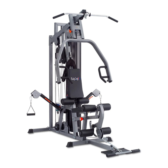
STRENGTH TRAINING SYSTEM
PRO
INSTRUCTION MANUAL
QUESTION?
As a quality home gym supplier we are committed to your complete satisfaction. If you have
questions, or find missing or damaged parts, we will guarantee your complete satisfaction through
our authorized dealer service centers or our home office customer service department. Please call
your local dealer for assistance or BodyCraft at 800-990-5556 (9:00 AM - 5:00 PM). Our trained
technicians will provide immediate assistance to you, free of charge.
Bodycraft is a division of Recreation Supply Inc.
P.O. BOX 181
Sunbury, OH 43074
78600A
Advertisement

Related Manuals for BodyCraft Xpress Pro


Summary of Contents for BodyCraft Xpress Pro
- Page 1 Please call your local dealer for assistance or BodyCraft at 800-990-5556 (9:00 AM - 5:00 PM). Our trained technicians will provide immediate assistance to you, free of charge.
-
Page 2: Before You Begin
Press before using the BODYCRAFT . Keep this manual for future reference. If you have additional questions, please call your local BODYCRAFT dealer or our customer service department at 800-990-5556 Monday through Friday, 9 a.m. until 5 p.m. Eastern Time. - Page 3 OVERVIEW 107 107 99 17 88 88 107 124 62 34...
-
Page 4: Table Of Contents
PARTS CHART NO. DESCRIPTION QTY. BASE FRAME REAR STABILIZER REAR UPRIGHT FRONT UPRIGHT TOP FRAME - bearing pre-installed TOP FRAME CONNECTOR GUIDE ROD TOP GUIDE ROD RETAINER PRESS ARM SELECTOR PRESS ARM RIGHT HANDLE OF PRESS ARM LEFT HANDLE OF PRESS ARM FRONT STABILIZER SEAT FRAME LEG EXTENSION ARM - bearing pre-installed... - Page 5 PARTS CHART NO. DESCRIPTION QTY. RED POP PIN CLUTCH LEVER OF CABLE ARM SPRING KNOB MAGMETIC SELECTOR PIN L PIN 3/4" BUSHING 1" X 200mm HAND GRIP 1" X 140mm HAND GRIP 1" X 70mm PRESS ARM STOPPER GRIP OF LAT BAR HOLDER (95mm) BIG PULLEY SMALL PULLEY OF SWIVEL ARM RUBBER DONUT...
- Page 6 PARTS CHART NO. DESCRIPTION QTY. 3/8" WASHER 5/16" WASHER 3/8" SPRING WASHER 5/16" SPRING WASHER 1" NYLON NUT 1/2" NYLON NUT 3/8" NYLON NUT 5/16" NYLON NUT TOP PLATE BOLT 3/8" X 3/4" INNER HEX SCREW ANKLE STRAP 3/8" X 1" INNER HEX SCREW 1"...
-
Page 7: Base Frame
T E P 1 ASSE M BL E M AI N FR AM E To ease the assembly process, do not tighten bolts until instructed. 1. Attach Rear Stabilizer(2) to Base Frame(1) using two 3/8"X3" Bolts(88), four 3/8" Washers(101) and two 3/8"... -
Page 8: Press Arm Selector
T E P 2 ASSE MBL E PR E SS AR M & C ABL E AR M ASSE MBL Y 1. Attach Press Arm Selector(8) to Top Frame with bearing pre-installed(5) by aligning holes and inserting 19.92mm Axle(31A). Lock into place with pre-installed set screw. 2. -
Page 9: Seat Frame
T E P 3 ASSE MBL E SE AT FR AME AND SE AT BAC K 1. Attach Seat Frame(11) to Front Upright(4) using two 3/8"X3" Bolts(88), four 3/8" Washers(101) and two 3/8" Nuts(107). Attach Seat Frame(11) to Base Frame(1) using 3/8"X4-1/2" Bolt(87), two 3/8" Washers(101) and one 3/8"... - Page 10 T OP C ABL E Assemble cables and pulleys simultaneously. Insert threaded end of Top Cable(80) into the slot in front of Top Frame(5)(Fig 1) and route over top of two pulleys mounted in Top Frame(5)(Fig 1, 2), over left side (as if sitting on seat) pulley in Press Arm Selector(8)(Fig 3, Step 1), under pulley mounted in Front Upright(4), over right side pulley in Press Arm Selector(8)(Fig 3, Step 2), then over pulley mounted in Front Upright(4)(Fig 3, Fig 4), down to top Double Pulley Block(26)(Fig 6), up and over left side pulley on Top Frame(5)(Fig 7), down and around...
-
Page 11: Cable Arm
AB C R UNC H C ABL E Route the AB Crunch Cable(78) through slot and over pulley on Front Upright(4)(Fig 1), down to the front pulley on top of Cable Arm Assembly(20)(Fig 2), then up to lower pulley on Double Pulley Block(26)(Fig 3), down through the rear pulley on Cable Arm Assembly(20)(Fig 4) to pulley on Base Frame(1)(Fig 2), then forward toward Leg Extension Arm(12). - Page 12 C ABL E AR M C ONNE C T I NG C ABL E Attach pulley on Base Frame(1) near weight stack as shown Fig 1 with ball end of cable toward weight stack. Route cable up to low pulley of Adjustable Pulley Block(25)(Fig 2), then down to pulley on Base Frame(1)(Fig 3), up to right side pulley in Top Frame(5)(Fig 4) and thread into the Single Pulley Block(27)(Fig 5).
-
Page 13: Pulley Guide Bracket
C ABL E AR M C ABL E Attach pulley and Pulley Guide Bracket(24) to Cable Arm Assembly(20) as shown in Fig 3 and Fig 4, Be certain that, when tightened, the Pulley Guide Brackets(24) do not interfere with the cable movement. -
Page 14: Adjustable Stopper
Step 12 The Cable Adjustment of X Press Pro a. The Cables should be tightened to the point just before the Top Plate lifts off the stack. In other words, if the Top Plate is not resting on the stack, you will need to add length, or, if there is slack in the cables, you will need to shorten the cables. - Page 15 Guide Rods (6). Enjoy many years of a Fit Lifestyle. Thank you for purchasing the Bodycraft X Press Home Gym. If You have any questions, please call your local BodyCraft dealer or call our customer service department at 800-990-5556...
Need help?
Do you have a question about the Xpress Pro and is the answer not in the manual?
Questions and answers