
Related Manuals for Portwell PIMB-09082


Summary of Contents for Portwell PIMB-09082
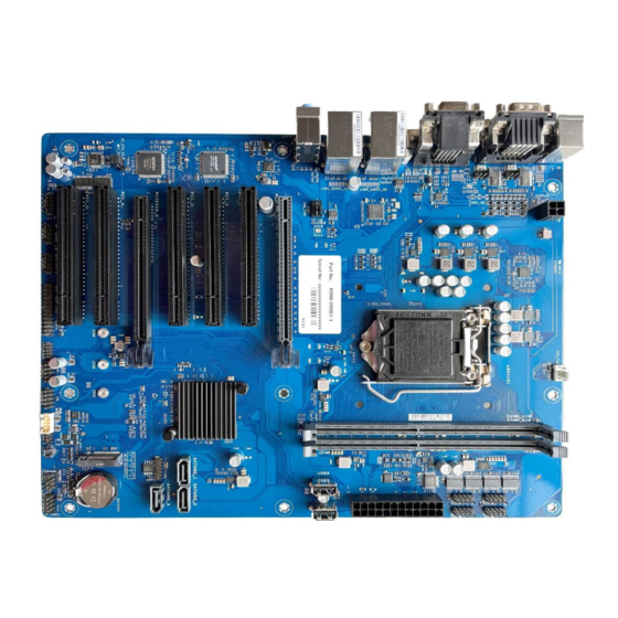
- Page 1 PIMB-09082 User Manual PIMB-09082 Portwell India PIMB-09082 (ATX Size motherboard) Version 1.1 Published date: July 2016 Color of board image is for representation purpose only. www.portwell.in User’s Manual PIMB-09082...
-
Page 2: Table Of Contents
PIMB-09082 User Manual Table of Contents 1. INTRODUCTION .................................... 3 2. SPECIFICATION ..................................... 4 2.1. S ................................5 UPPORTED PERATING YSTEMS 3. MECHANICAL DIMENSION & HARDWARE CONFIGURATION ......................6 ............................................6 3.1. M ................................... 6 ECHANICAL IAGRAM 3.2. H ..................................7... -
Page 3: Introduction
Product names, logos, brands, and other trademarks featured or referred to within this User ‘s guide or the Portwell website, are the property of their respective trademark holders. These trademark holders are not affiliated with Portwell, our products, or our website. -
Page 4: Specification
PIMB-09082 User Manual 2. Specification Intel ® socket 1151 for 7 Gen Intel ® Core™ i7/ i5/ i3, Pentium ® , and Celeron ® Processors Supports Intel ® 14nm CPU Supports up to 65W Chipset Intel ® H110 Chipset Memory 2 x U-DIMM, max.32GB, DDR4 2400/2133 MHz SDRAM... -
Page 5: Supported Operating Systems
PIMB-09082 User Manual GPIO 1 x 8-bit GPIO header Manageability WfM 2.0, DMI 2.0, WOL by PME Watch dog timer Power requirement AT/ATX mode Operation 0~60°C Temperature Non-Operation -40~85°C Temperature Relative Humidity 0%~85% Windows® 7 (32/64bit ) Windows® 10 (64bit ) Windows® 10 IoT Enterprise Ubuntu, RedHat Enterprise... -
Page 6: Mechanical Dimension & Hardware Configuration
PIMB-09082 User Manual 3. Mechanical Dimension & Hardware Configuration 3.1. Mechanical Diagram NOTE: The audio codec may vary between motherboards, please consult your sales window for the motherboard’s exact codec type. www.portwell.in User’s Manual PIMB-09082... -
Page 7: Hardware Configuration
PIMB-09082 User Manual 3.2. Hardware Configuration Connectors/Jumpers/Slots COM RING/+5V/+12V selection (COM1/2_SEL) ATX power connectors (24-pin EATXPWR, 4-pin ATX12V) CPU and chassis fan headers (4-pin CPU_FAN, 4-pin CHA_FAN) Intel ® LGA1151 CPU socket DDR4 U-DIMM slots COM Port headers (10-1 pin COM3 - COM8) USB 2.0 headers / connectors (10-1pin USB56, USB78 / USB9, USB10) - Page 8 PIMB-09082 User Manual 3.2.2 System memory This motherboard comes with two Double Data Rate 4 (DDR4) Dual Inline Memory Module (DIMM) sockets. The figure below illustrates the location of the DDR4 DIMM sockets: Channel Sockets Channel A U-DIMM_A1* Channel B U-DIMM_B1* www.portwell.in...
-
Page 9: Jumpers & Connectors
PIMB-09082 User Manual 4. Jumpers & Connectors Jumpers 4.1. 4.1.1. Clear RTC RAM (2-pin CLRTC) This header allows you to clear the CMOS RTC RAM data of the system setup information such as date, time, and system passwords. Connector type Header 1x2p, 2.54mm pitch, S/T... - Page 10 PIMB-09082 User Manual 4.1.2. COM Ring/+5V/+12V selection jumper (6-pin COM1/2_SEL) COM2_SEL COM1_SEL Pins Setting +12V Ring (Default) www.portwell.in User’s Manual PIMB-09082...
- Page 11 PIMB-09082 User Manual 4.1.3. Chassis intrusion header (4-1 pin_CHASSIS) This header is for a chassis-mounted intrusion detection sensor or switch. Connect one end of the chassis intrusion sensor or switch cable to this connector. The chassis intrusion sensor or switch sends a low-level signal to this connector when a chassis component is installed. The signal is then generated as a chassis intrusion event.
- Page 12 PIMB-09082 User Manual 4.1.4. AT/ATX mode selection (3-pin AT_ATX_SEL) Connector type Header 1x3p, 2.54mm pitch Pins Setting 1-2 (Default) ATX Mode AT Mode www.portwell.in User’s Manual PIMB-09082...
- Page 13 PIMB-09082 User Manual 4.1.5. WDT Enable jumper (2-pin WDT_EN) A watchdog timer is an electronic timer that is used to detect and recover from computer malfunctions. The HW WDT (watchdog timer) Enable jumper allows the HW watchdog resets the system automatically even when the system crashes.
-
Page 14: Rear Panel Connectors
PIMB-09082 User Manual 4.2. Rear Panel Connectors PS/2 This Port is for PS/2 Mouse & keyboards COM 2 & COM RS232/RS422/RS485 ports connect modems, or other devices that conform serial specification This 15-Pin port for VGA monitor or other VGA compatible devices... -
Page 15: Internal Connectors
PIMB-09082 User Manual 4.3. Internal Connectors 4.3.1. ATX Power Connectors (24-pin EATXPWR, 4-pin ATX12V) Correctly orient the ATX power supply plugs into these connectors and push down firmly until the connectors completely fit. EATXPWR ATX 12V 4.3.2. CPU and chassis fan headers (4-pin CPU_FAN, 4-pin CHA_FAN) - Page 16 PIMB-09082 User Manual 4.3.3. COM Port headers (10-pin COM3 - COM8) COM 5 These headers are for serial (COM) ports. Connect the serial port COM 6 cables to these headers, then install the module to a slot opening at COM 7...
- Page 17 PIMB-09082 User Manual 4.3.5. SATA 6.0Gb/s ports (7-pin SATA6G_1/2/3) These ports connect to SATA 6.0 Gb/s hard disk drives or an optical drive via SATA 6.0 Gb/s signal cables. SATA6G_1 SATA6G_2 SATA6G_3 4.3.6. TPM Header (14-1 pin TPM) This header supports a Trusted Platform Module (TPM) system with a Serial Peripheral Interface (SPI), allowing you to securely store keys, digital certificates, passwords, and data.
- Page 18 PIMB-09082 User Manual 4.3.7. M.2 Slot (Socket 3) This slot allows you to install an M.2 SSD module. This slot supports M Key and 2242/2260/2280 storage devices 4.3.8. Front panel system panel connector (10-1 pin F_PANEL) Connector Type Header 2x5p, K10, 2.54mm pitch www.portwell.in...
- Page 19 PIMB-09082 User Manual 4.3.9. Speaker header (4-pin SPEAKER) The 4-pin header is for the chassis-mounted system warning speaker. The speaker allows you to hear system beeps and warnings. Connector Type HEADER 1x4p, 2.54mm pitch, S/T 4.3.10. I2C Header The I2C (Inter-Integrated Circuit) header allows you to connect an I2C compatible...
- Page 20 PIMB-09082 User Manual 4.3.11. General purpose input/output header (GPIO_CON) This header is for a general-purpose input/output module which allows you to customize the digital signal input/output. Connector Type WAFER HD 2x5p, 2.0mm pitch, S/T 4.3.12. LPC Debug header This header allows connection to a LPC Debug card.
- Page 21 PIMB-09082 User Manual 4.3.13. LPT header (26-1 pin LPT) Sd The LPT (Line Printing Terminal) header supports devices such as a printer. LPT is standardized as IEEE 1284, which is the parallel port interface on IBM PC- compatible computers. 4.3.14.
-
Page 22: Bios
PIMB-09082 User Manual 5. BIOS 5.1. BIOS Setup program Use the BIOS Setup program to update the BIOS or configure its parameters. The BIOS screens include navigation keys and brief online help to guide you in using the BIOS Setup program Press <Delete>... -
Page 23: Menu Bar
PIMB-09082 User Manual 5.2. Menu bar The menu bar on top of the screen has the following main items Main For changing the basic system configuration Advanced For changing the advanced system settings Hardware Monitor For displaying the system temperature and changing the fan settings... -
Page 24: Main Menu
PIMB-09082 User Manual 5.3. Main Menu The Main menu provides you an overview of the basic system information, and allows you to set the system date, time, language, and security settings. System Date [Day MM/DD/YYYY] : Allows you to set the system date System Time [HH:MM:SS] : Allows you to set the system time 5.4. - Page 25 PIMB-09082 User Manual 5.4.1. PCH-FW Configuration TPM Device Selection: This item allows you to select the TPM device. Configuration options: [dTPM] [PTT] 5.4.2. Trusted Computing Security Device Support: This item allows you to enable or disable BIOS support for security devices. Configuration options: [Disabled] [Enabled] www.portwell.in...
- Page 26 PIMB-09082 User Manual 5.4.3. CPU Configuration The items in this menu show CPU-related information the BIOS automatically detects. Note: The items shown in the submenu may be different depending on the type of CPU installed Intel (VMX) Virtualization Technology: Enabled: a VMM can utilize the additional hardware capabilities provided by Vanderpool Technology.
- Page 27 PIMB-09082 User Manual 5.4.4. Graphics Configuration Allows You To Select A Primary Display From Igfx, Peg And Pci Graphical Devices. • Primary Display: Allows You To Select Which Of The Igfx/Peg/Pci Graphics Device Should Be The Primary Display. Options: [Auto] [Igfx] [Peg] [Pci] •...
- Page 28 PIMB-09082 User Manual Pcie X16_2 Slot: This Item Allows You To Enable Or Disable The Pcie X16_2 Slot Aspm: This Item Allows You To Control The Active State Power Management On Both Nb (North Bridge) Side And Sb (South Bridge) Side Of The Dmi Link. Options: [Disabled]...
- Page 29 PIMB-09082 User Manual 5.4.6. CSM Configuration: Compatibility Support Module Configuration • CSM Support: Allow you to enable/disable the CSM support. • Network: Controls the execution of UEFI and Legacy PXE OpROM. options: [Do not launch] [UEFI] [Legacy] • Storage: Controls the execution of UEFI and Legacy Storage OpROM. options: [Do not launch] [UEFI] [Legacy] •...
- Page 30 PIMB-09082 User Manual Nct6116d Super Io Configuration • Serial Port 1 Configuration: Com1 Control: Allows You To Select The Com1 Mode. Configuration Options: [Rs232] [Rs422] [Rs485] • Serial Port 2 Configuration Com2 Control: Allows You To Select The Com2 Mode. Configuration Options: [Rs232] [Rs422] [Rs485] •...
- Page 31 PIMB-09082 User Manual 5.4.8. Serial Console Configuration Com1~Com8 • Console Redirection: Allows You Enable Or Disable The Console Redirection Feature. Configuration Options: [Enabled] [Disabled] 5.4.9. SATA Configuration Sata6g_1/2/3: Allow You To Enable/Disable The Sata6g_1/2/3 Port. Configuration Options: [Disabled] [Enabled] Hot Plug: These Items Allow You To Enable/Disable Sata Hot Plug Support. Configuration Options: [Disabled] [Enabled] M.2: Allow You To Enable/Disable The M.2 (Socket3).
- Page 32 PIMB-09082 User Manual 5.4.10. USB Configuration Lan1_U32g1_1/2, Lan2_U32g1_3/4: Allows You To Enable Or Disable Usb Port. Once Set To [Disabled], Any Usb Devices Plugged Into The Connector Will Not Be Detected By Bios Or Os. Configuration Options: [Disabled] [Enabled] Usb5-10: Allows You To Enable Or Disable Usb Port. Once Set To [Disabled], Any Usb Devices Plugged Into The Connector Will Not Be Detected By Bios Or Os.
- Page 33 PIMB-09082 User Manual 5.4.12. APM Configuration Erp Ready: Allows You To Switch Off Some Power At S5 To Get The System Ready For Erp Requirement. When Set To [Enabled], All Other Pme Options Will Be Switched Off. Configuration Options: [Disabled] [Enabled]...
- Page 34 PIMB-09082 User Manual 5.4.13. EzFlash Enter Ez-Flash Mode: This Item Allows You To Run Ezflash Utility. When You Press <Enter>, A Confirmation Message Appears. Use The Left/Right Arrow Key To Select Between [Yes] Or [No], Then Press <Enter> To Confirm Your Choice.
- Page 35 PIMB-09082 User Manual 5.4.15. Network Stack Configuration Network Stack: This Item Allows User To Disable Or Enable The Uefi Network Stack. Configuration Options: [Disabled] [Enabled] Ipv4 Pxe Support: This Item Allows User To Disable Or Enable The Ipv4 Pxe Boot Support.
-
Page 36: Hardware Monitor Menu
PIMB-09082 User Manual Hardware Monitor menu 5.5. The Items In This Menu Provide You An Overview Of System Status Including Temperature, Fan Speed And Voltage, And Allow You To Configure The Smart Fan. Smart Fan Mode: Allows You To Select The Smart Fan Mode. Configuration Options: [Disabled]... -
Page 37: Security Menu
PIMB-09082 User Manual 5.6. Security menu This Menu Allows A New Password To Be Created Or A Current Password To Be Changed. The Menu Also Enables Or Disables The Secure Boot State And Lets The User Configure The System Mode State. - Page 38 PIMB-09082 User Manual To Clear A User Password: 1. Select The Clear User Password Item And Press <Enter>. 2. Select Yes From The Warning Message Window Then Press <Enter>. Secure Boot Secure Boot: Secure Boot Can Be Enabled If The System Is Running In User Mode With Enrolled Platform Key (Epk) Or If The Csm Function Is Disabled.
-
Page 39: Boot Menu
PIMB-09082 User Manual 5.7. Boot Menu The Boot Menu Items Allow You To Change The System Boot Options. Boot Configuration: Chassis Intrude: Allows You To Enable Or Disable The Chassis Intrusion Detection Function. Configuration Options: [Disabled] [Enabled] Setup Prompt Timeout: Allows You To Set The Number Of Seconds To Wait For Setup Activation Key. - Page 40 PIMB-09082 User Manual Usb Support [Disabled]: All Usb Devices Will Not Be Available Until Os Boot Up For A Fastest Post Time [Full Initial]: All Usb Devices Will Be Available During Post. This Process Will Extend The Post Time. [Partial Initial]: For A Faster Post Time, Only The Usb Ports With Keyboard And Mouse Connections Will Be Detected.
-
Page 41: Exit Menu
PIMB-09082 User Manual 5.8. Exit Menu The Boot Menu Items Allow You To Change The System Boot Options. Save Changes & Exit This Option Allows You To Save Your Changes And Exit The Setup Program. When You Select This Option Or If You Press <Esc>, A Confirmation Window Appears. Select Yes To Save Changes And Exit.
Need help?
Do you have a question about the PIMB-09082 and is the answer not in the manual?
Questions and answers