Table of Contents
Advertisement
Quick Links
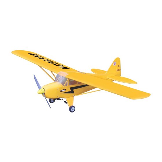
PIPER J - 3 CUB 26s
0.25-0.32 cu. in. displacement 2-stroke
0.30 cu. in. displacement 4-stroke
Require : 4 - channel
s
Wing Span
Wing Area
Flying Weight
Fuselage Length
Warning! This model is not a toy.
It is designed for maximum performance. Please seek advice if one is not familiar with this kind
of electric powered precision model. Operating this model without prior preparation may cause
injuries. Remember, safety is the most important thing. Always keep this instruction manual at
hand for quick reference.
A002SPO24781009
Specifications
*Specifications are subject to change without notice.*
radio / 4 standard
w
51.0 in / 1300 mm
419 sq in / 27.0 sq dm
3.3 lbs /1500 g
33.0 in / 840 mm
INSTRUCTION MANUAL
servos
FACTORY PRE-FABRICATED
ALMOST-READY-TO-FLY (ARF) SERIES
MADE IN CHINA
Advertisement
Table of Contents

Related Manuals for THE WORLD MODELS PIPER J-3 CUB 26s


Summary of Contents for THE WORLD MODELS PIPER J-3 CUB 26s
- Page 1 INSTRUCTION MANUAL PIPER J - 3 CUB 26s 0.25-0.32 cu. in. displacement 2-stroke 0.30 cu. in. displacement 4-stroke Require : 4 - channel radio / 4 standard servos Specifications Wing Span 51.0 in / 1300 mm Wing Area 419 sq in / 27.0 sq dm Flying Weight 3.3 lbs /1500 g Fuselage Length...
-
Page 2: Before You Begin
PIPER J - 3 CUB 26s I N D E X BEFORE YOU BEGIN P. 1 PARTS LIST P. 2 ASSEMBLY P. 3 -10 SAFETY PRECAUTIONS P.10 BEFORE YOU BEGIN Read through the manual before you begin, so you will have an overall idea of what to do. Check all parts. - Page 3 Parts List 1. MAIN WING -- 1 pair 12. MAIN WHEEL Ø50mm -- 2 sets COLLAR Ø3.1mm w/ set screw -- 4 sets 2. WING JOINER 6x20x87mm -- 1 pc. BALSA 2x80x90mm (Main Landing Gear Cover) -- 1 pair PLYWOOD 9x9x12mm -- 4 pcs 3.
-
Page 4: Aileron Servo
Main Wing Apply instant type CA glue to both sides of each hinge. Please dry fit wing joiner into left and right wing to make sure they fit with the proper Main Wing dihedral angle, mark the wing joiner if necessary. Apply epoxy glue to both sides of all surfaces in contact. -
Page 5: Wing Struts
Wing Struts 362mm 71mm Screw PA2.6x12mm 90mm PA2.6x12mm Bottom View Vertical Fin / Horizontal Stabilizer (Stabilizer) Temporary install the main wing, adjust leveling of the stabilizer to make it as (Main Wing) parallel to the main wing as possible. B=B' Apply instant type CA glue to both sides of each hinge. -
Page 6: Engine Mount
Engine Mount M3x20mm Socket Head Screw d3xD7mm Washer Engine Mount PL5111020 d3xD7mm Washer M3x20mm Socket Head Screw Lead the 1.2mm throttle rod through the plastic tube and attach the throttle rod Engine to the throttle lever on the engine. Installed Engine Position Socket Head Screw M3x25mm Ø45mm... -
Page 7: Landing Gear
Landing Gear HM3x16mm Screw d3xD7mm Washer M3 Nut M3 Nut Aluminum Plate 1.5mm d3xD7mm Washer 3.5mm HM3x16mm Landing Gear PA3x10mm Screw PA3x10mm Mounting Plate 12x20mm Bottom View Landing Gear 3mm Set Screw Plywood 9x9x12mm 3.1mm Collar Balsa 2x80x90mm Bottom View A002SPO24781009... - Page 8 Canopy PWA2.3x8mm Screw d1.5xD6.5mm Silicon Grommet d1.5xD6.5mm PWA2.3x8mm Silicon Grommet Please refer to the attached sheet for Cowling usage of the transparent 3D template. First insert the grommet to PWA2.6x12mm Screw the cowling then apply screw. d1.5xD6.5mm Silicon Grommet 1.5mm PWA2.6x12mm Silicon Grommet d1.5xD6.5mm...
-
Page 9: Radio Equipment
Ø6x5mm Battery Rudder Servo Rudder Pushrod Ø1.8x485mm Elevator Pushrod Ø1mm pilot holes for The World Models tri-horn are pre-drilled. PB2x10mm Screw Please look for pin-hole marks at under side of control surfaces. PB 2 x 10mm Clevis Fuel Tube Ø6x5mm... -
Page 10: Rudder Pushrod
Rudder Pushrod PB2x10mm Screw Fuel Tube Ø6x5mm Clevis Tri-Horn Ø1mm pilot holes for The PB2x10mm M3x14mm World Models tri-horn are pre-drilled. Please look for pin-hole marks at side of control surfaces. Bottom View Main Wing/ Wing Struts HM3x30mm HM3x30mm Screw d3xD12mm Washer Plastic Plate1x24x84mm d3xD12mm Washer... -
Page 11: Control Throws
Adjust the control throws as shown in Control Throws the diagram. These throws are good for general flying. You can adjust according to your personal preference. Rudder 14mm 14mm Elevator 28mm 28mm Aileron C.G. The ideal C.G. position is 55mm (2.16 in) behind the leading edge measured at where the wing meets the fuselage. - Page 12 LINKAGE CONNECTOR HW7111050 & HW7111060 Drill 2mm hole at servo horn. Insert linkage connector into servo horn. Make sure shoulder of screw is cleared from servo horn. Add washer to reduce play if necessary. Shoulder Tighten up the round nut against the shoulder.
- Page 13 Product Registration Form (US Customers) We would like to share with you any relevant information regarding your model, including product news and free upgrade parts when applicable. Please fill in the following and send to Air orne Models, 4749-K,Bennett Drive, Livermore, CA 94551 USA 1.Name: 2.Address: 3.Phone #:...
- Page 14 Usage of the transparent 3D template This transparent 3D template is used for position guidance of the actual cutting of the pre-painted cowling. Simply cut the transparent 3D template to fit your engine and exhaust pipe, then slide onto the actual cowling and use as template to mark the openings required for final cutting.
-
Page 15: Optional Parts
Optional Parts Fuel Filler 180mm Extension Code No. Size Package Code No. Size Package PL8110030 KW0011800 180mm 1 set 15 x 22 x 49mm 1 x 1 pc 180mm Y-Cord Code No. Size Package KW0021800 180mm 1 pc Clevis Wrench Code No. - Page 16 A002SPO24781009...
Need help?
Do you have a question about the PIPER J-3 CUB 26s and is the answer not in the manual?
Questions and answers