Table of Contents
Advertisement
Quick Links
INSTRUCTIONS
A radio-controlled model is not a toy and is not intended for persons under 16 years old. Keep
this kit out of the reach of younger children, as it contains parts that could be dangerous. A radio-
controlled model is capable of causing serious bodily injury and property damage. It is the buyer's
responsibility to assemble this aircraft correctly and to properly install the motor, radio, and all other
equipment. Test and fly the finished model only in the presence and with the assistance of another
experienced R/C flyer. The model must always be operated and flown using great care and common
sense, as well as in accordance with the Safety Code of the Academy of Model Aeronautics
(www.modelaircraft.org). We suggest you join the AMA and become properly insured prior to flying
this model. Also, consult with the AMA or your local hobby dealer to find an experienced instructor in
your area. Per the Federal Communications Commission, you are required to use only those radio fre-
quencies specified "for Model Aircraft."
Carl Goldberg Products has inspected and certified the components of this aircraft. The company urges the buyer to perform his
own inspection, prior to assembly, and to immediately request a replacement of any parts he believes to be defective for their
intended use. The company warrants replacement of any such components, provided the buyer requests such replacement with-
in a period of 90 days from the date of purchase and provided the defective part is returned, if so requested by the company.
No other warranty, expressed or implied, is made by the company with respect to this kit. The buyer acknowledges and under-
stands that it is his responsibility to carefully assemble the finished flying model airplane and to fly it safely. The buyer hereby
assumes full responsibility for the risk and all liability for personal or property damage or injury arising out of the buyer's use of the
components of this kit.
CARL GOLDBERG PRODUCTS, LTD.
P.O. Box 818 Oakwood GA 30566 Phone #678-450-0085 Fax # 770-532-2163 www.carlgoldbergproducts.com
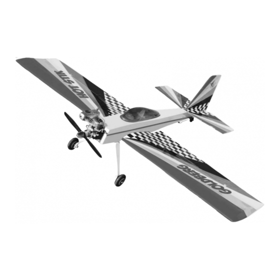
Hot Stik ARF
LIMITED WARRANTY
© Copyright 2005 Carl Goldberg Products LTD
WARNING
1
TM
Advertisement
Table of Contents

Related Manuals for Carl Goldberg Products Hot Stik ARF


Summary of Contents for Carl Goldberg Products Hot Stik ARF
- Page 1 LIMITED WARRANTY Carl Goldberg Products has inspected and certified the components of this aircraft. The company urges the buyer to perform his own inspection, prior to assembly, and to immediately request a replacement of any parts he believes to be defective for their intended use.
- Page 2 Hot Stik ARF against flutter due to improper set-up or excessive speed maneuvers. having said that, we believe you will find the Hot Stik ARF to be one of the most responsive, Building supplies needed in-the-grove aircraft on the market. Just remem-...
- Page 3 #930 1” Black & White Checkered COVERING The Hot Stik ARF is covered in a premium polyester film chosen by many of the world's top flyers for its beauty, toughness, and ease of application and repair. It is not uncommon for ARF's to develop a few wrinkles in transit.
-
Page 4: Fuselage Assembly
Fuselage Assembly COLLECT THE FOLLOWING ITEMS (1) ALUMINUM LANDING GEAR (2) 5/32” AXES (2) AXLE NUTS (2) WHEEL COLLARS (2) 6-32 X 1” BOLTS (2) 2-1/2” WHEELS Bolt the landing gear in place using the two 6- (2) FLAT WASHERS 32 bolts and flat washers. - Page 5 slot for elevator wire Using a pencil, make a mark along the side of Find the center of the stab at the trailing edge the fuselage on both side of the stab. and make a mark at the location. Place the stab on the fuselage and align the center mark at the rear.
- Page 6 Install the elevator on the stab pushing the hinges in until the pins are flush against the trailing edge of the stab. When all are in place, remove the pins and push the elevators flush against the stab. Mix some 5-minute epoxy and force into the holes for the joiner wire in the elevators.
- Page 7 Remove the covering on the post of the fin, leave the back covered where it shown on the rear. Make sure covering is removed on the bottom of the fin where it sits on the stab. Mix some epoxy and install the fin. Make sure it is centered on the front.
-
Page 8: Engine Mounting
Locate the rudder and install the hinges using Engine Mounting pins in the holes to make sure the hinges go half way into the rudder. COLLECT THE FOLLOWING ITEMS (2) NYLON MOTOR MOUNTS (2) 4MM X 25MM BOLTS (2) FLAT WASHERS Mix some epoxy and force into the hole in the rudder where the tail wheel tiller are goes.Install the rudder on the fin and push... -
Page 9: Wing Assembly
Place your engine on the mounts and mark Install the two servos in the cutout provided the location of the engine mounting holes on with the output arm to the rear. You will need the mounts. Remove the engine and drill a a 12”... -
Page 10: Rudder Servo Installation
silicone tubing keeper Repeat for the other three horns. Install the pushrod in the servo output arm and retain with the nylon swing in keeper. Push the silicone clevis keeper down to the control horn. Repeat for the other aileron and both flaps. Rudder Servo Installation 1/16”... - Page 11 Measure 1/2” from the bottom of the rudder and 3/8” back from the hinge line and drill a 9/64” hole for the rudder control horn. Install the 6-32 x 2-1/2” threaded rod with a nut and washer on each side. Center the rod in the rudder.
-
Page 12: Elevator Servo Installation
Elevator Servo Installation Install the elevator servo in the opening pro- vided in the tray. The opening is made wide so Install the elevator control horn on the inboard you can align different length servo arms with edge of the elevator on the right side of the the pushrod. -
Page 13: Throttle Servo Installation
Throttle Servo Installation Open the throttle on the engine to full and set the servo to full throttle. Mark the pushrod and make a 90 degree bend at the mark. The bend will need to be made down into the fuselage because of the close clearance of the wing. -
Page 14: Battery Installation
top of tank Receiver Switch and Battery Installation Insert the cap in the tank, making sure the vent line is at the top of the tank. The top of the tank is the one closes to the cap. The clunk should be 1/4” off the bottom of the tank. Tighten the center screw to retain the cap in the tank. -
Page 15: Final Assembly
Final Assembly The battery can be wrapped in form and fitted into the opening. Canopy Installation Locate the 1/4-20 nylon bolt and the wing bolt reinforcement plate. Bolt the wing in place. COLLECT THE FOLLOWING ITEMS (1) PLASTIC COCKPIT INSERT The CG should be 4”...
Need help?
Do you have a question about the Hot Stik ARF and is the answer not in the manual?
Questions and answers