Table of Contents
Advertisement
Quick Links
MA
TRIX 40
MA
TRIX 40
EXTREME 3-D ARF
EXTREME 3-D ARF
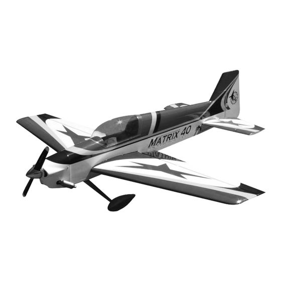
Congratulations on your purchase of the Matrix 40 Extreme 3-D ARF. This is a very unique dual-
purpose aircraft, capable of flying any FAI pattern sequence with ease, while exhibiting remarkable
3-D capabilities. Every effort has been made to produce a lightweight, straight, easy to assemble
aircraft. Because of its oversize control surfaces which are double beveled to allow for extreme
throws, great care must be taken in the set-up and flying of this airplane. Quality hardware compo-
nents have been provided to allow for 3D set-up while maintaining adequate mechanical advantage
to eliminate flutter. It is you responsibility as an advanced pilot to fly the aircraft in an intelligent man-
ner. THROTTLE MANAGEMENT IS A MUST!!!!!!! Carl Goldberg Products has flown the Matrix 40
through a very rigorous flight-testing schedule and have stressed the airframe beyond all practical
parameters without a single failure. Carl Goldberg Products will NOT warrant the Matrix 40 against
flutter due to improper set-up or excessive speed maneuvers. having said that, we believe you will
find the Matrix 40 to be one of the most responsive, in-the-grove aircraft on the market. The Matrix
40 excels at high-alpha maneuvers including Harriers (both upright and inverted), high-alpha rolls,
and high-alpha knife edge. Torque rolls, waterfalls, knife edge loops and elevators are all within the
performance parameters of this unique aircraft. Just remember to use common sense when flying
this high performance machine.
CARL GOLDBERG PRODUCTS, LTD.
P.O. Box 88 Oakwood GA 30566 Phone #678-450-0085 Fax # 770-53-63 www.carlgoldbergproducts.com
PT. #6135 6/03
' Copyright 2003 Carl Goldberg Products, Ltd.
1
Advertisement
Table of Contents

Related Manuals for Carl Goldberg Products MATRIX 40 EXTREME 3-D ARF


Summary of Contents for Carl Goldberg Products MATRIX 40 EXTREME 3-D ARF
- Page 1 EXTREME 3-D ARF EXTREME 3-D ARF Congratulations on your purchase of the Matrix 40 Extreme 3-D ARF. This is a very unique dual- purpose aircraft, capable of flying any FAI pattern sequence with ease, while exhibiting remarkable 3-D capabilities. Every effort has been made to produce a lightweight, straight, easy to assemble aircraft.
- Page 2 We are very proud of the construction of the Matrix 40 and all of our other ARF aircraft. Each air- craft is jig built to insure a straight true airframe. Every effort is made to build as light an aircraft as possible.
-
Page 3: Parts List
Parts List COWL HARDWARE 1. Fuselage 1. (4) 2mm x10mm screws for cowl mounting 2. Fiberglass Cowl 3. One piece wing /ailerons 4. Stab/elevator assembly 5. Rudder Control System 6. Fiberglass wheel pants 7. Canopy 1. (5) Nylon control horns 8. - Page 4 Mounting Stab Before beginning assembly of your Matrix 40, we highly recommend that you study this manu- al in its entirety. You should begin planning your radio installation based on your choice of engine and equipment from the beginning, as space is limited within the fuselage of the Matrix 40.
- Page 5 7. Turn the wing over and remove the covering 4. When satisfied with the alignment, use a dry- over the wing bolt holes. Slide the front wing erase marker to draw a line on side of the stab, dowels in to the holes in the fuselage saddle. top and bottom where it meets the fuselage.
-
Page 6: Control Horns
Control Horns 2. Install the e-z hinges in the stab using a pin in the center of each to make sure they stay aligned. 2-56 x 3/4” SCREWS CONTROL PLACE CONTROL HORN HORN AT HINGE LINE SNAP LINK 3.Install the elevators on the hinges and with the elevators pushed tightly against the stab, remove the pins. - Page 7 5. using pins to center the hinges as was done with the elevators, install the rudder. Deflect to full throw and glue the hinges in place using thin CA. 5 inches 3. Place tailwheel on the bottom of the fuselage so that the wire is flush with the back of the fuselage and centered on the bottom.
- Page 8 Elevator Bellcrank Elevator Bellcrank Elevator Pull-Pull Wire 4-40 Set Screw #2 x 1/2” Screw Crimp the brass tube Plastic Collar 4-40 Set Screw #2 x 1/2” Screw You may need only one spacer 3/32” Mark and drill a 3/32” hole through the aluminium shaft, then mount the con- #2 x 1/2”...
- Page 9 open hole 6. you can mount the hatch cover on the bottom 4. Using your #11 blade, open the hole on both of the fuselage using clear tape or screws (not sides of the fuselage. Install the mounts in both included) sides using the 2mm screws supplied.
-
Page 10: Rudder Servo
11. Locate the two 2-56 x 10” elevator pushrods Rudder Servo and thread a clevis on each. Install the clevis on the elevator horn and mark the location of the bend at the bellcrank. Bend the rod 90 degrees and cut to a length of 3/8”. 1. - Page 11 Ailerons 1. Hinge the ailerons on to the wing using pins and Thin CA just like the elevators and rudder. Bottom side of wing 4. Install a control horn on the servo and center the servo with the arm paralle to the hinge line. 8-1/4”...
- Page 12 Landing Gear and Wheel Pants The pants are just alike except for this mounting pad. drill a 5/32” hole into this mounting pad, 1/4” up (or into the bottom of that pad) from the bottom edge and centered on the wheel open- ing.
-
Page 13: Engine Mounting
Engine Mounting 4-3/4” Note: The distance that is shown is for using a Carl Goldberg spinner. If you are going to use a different spinner, the front of the cowl needs to 1. Locate be 4-5/8” from the firewall. 2- motor mounts 3. - Page 14 Fuel Tank 5. Align the motor on the firewall. Center the engine on the off center vertical line and the hor- izontal line. Drill holes on the marks using a 1. Locate the fuel tank and hardware. 3/16” drill. Insert the blind nuts into the rear of the fire wall and tighten using washers and lock washer (use thread lock).
-
Page 15: Cowl Installation
3. Install the tank in the fuselage in the notches provided in the bulkhead, and hold in place with foam(not provided). Attach the fuel lines(not provided) to the three metal lines and route through the hole in the firewall and to your engine. -
Page 16: Decal Location
Canopy Decal Location 1. Locate the canopy and trim to the scribe line. It is a good idea to trim about 1/8” outside the line at first and then trim to fit so as not to get it too small. Clean model surfaces thoroughly before applying decals. - Page 17 The Elevator This maneuver has your plane drop vertically in a nose high attitude, depending on wind condi- tions any where from a 45 degree angle in low wind to almost backwards in higher wind condi- tions. To perform it, at a high altitude with high rates on, pull your throttle back and feed in the elevator until you have the full high rate applied.
- Page 18 The Waterfall This maneuver has your plane flipping around the axis of the wing, while dropping. Starting from a high altitude, go to low throttle and grad- ually pull the nose up to near vertical. Just when the plane is about the stall, give it full down elevator and full power.
Need help?
Do you have a question about the MATRIX 40 EXTREME 3-D ARF and is the answer not in the manual?
Questions and answers