Advertisement
Quick Links
Mechanical Installation Instructions
Figure 1: Dimensions are for a standard ComNet
Rack Module:
The unit is designed to be installed in the ComNet 19-inch (483-mm) EIA standard card-cage rack, the C1-US,
C1-EU, or the C1-CH. Follow these guidelines to install rack cards after performing module setup procedures.
C1-US, C1-EU, or the C1-CH Card Cage Racks
CAUTION: Although the units are hot-swappable and may be installed without turning power off to the rack,
ComNet recommends that the power supply be turned off and that the rack power supply is disconnected
from any power source. Note: Remove electrical connector before installing in card cage rack.
1. Make sure that the card is oriented right side up, and slide it into the card guides in the rack until the
edge connector at the back of the card seats in the corresponding slot in the rack's connector panel.
Seating may require thumb pressure on the top and bottom of the card's front panel.
CAUTION: Take care not to press on any of the LEDs.
2. Tighten the two thumb screws on the card until the front panel of the card is seated
against the front of the rack.
™
one slot module.
.156 [3.96 mm]
.313 [7.95 mm]
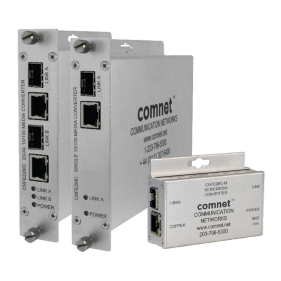
CNFE2MC
Communication Networks
3 Corporate Drive • Danbury, CT 06810 • USA
Tel: 203-796-5300 • Toll Free: 1-888-678-9427
www.comnet.net
Installation Considerations
This fiber-optic link is supplied as
a Standalone/Rack module.
Units should be installed in dry
locations protected from extremes
of temperature and humidity.
Standalone Module:
The unit is provided with a mounting
plate with holes for two No. 6 pan
head screws (3-mm or 3.55-mm).
The type of screws must be suitable
for the surface where a module will
be mounted. See figure 1.
1. Determine where the module will be
installed, and ensure that there is
adequate space at both ends for
making the various cable
connections and for reading the
diagnostic LEDs.
2. Attach the module to a flat surface
using two mounting screws.
(Not Supplied)
INS_CNFE2MC_REVA
04/07/09
Page 1
Advertisement

Related Manuals for Comnet CNFE2MC


Summary of Contents for Comnet CNFE2MC
- Page 1 (Not Supplied) Rack Module: The unit is designed to be installed in the ComNet 19-inch (483-mm) EIA standard card-cage rack, the C1-US, C1-EU, or the C1-CH. Follow these guidelines to install rack cards after performing module setup procedures. C1-US, C1-EU, or the C1-CH Card Cage Racks...
- Page 2 CNFE2MC SINGLE 10/100 MEDIA CONVERTER INSTALLATION INSTRUCTIONS LINK A: YELLOW: Link = Highest Data Rate (100 Mb/s) GREEN: Solid = No Activity Blinking = Activity GREEN YELLOW RJ45 GREEN = Powered On RJ45: YELLOW: Link = Highest Data Rate (100 Mb/s)
- Page 3 SFP-(x) Installation/Removal CAUTION: - The Fiber Optic sub-module is static sensitive. Use static handling precautions when installing or removing the sub-module. - Protect your SFP sub-modules by inserting clean dust plugs into the SFP sub-modules after the optical fiber is extracted from them.
Need help?
Do you have a question about the CNFE2MC and is the answer not in the manual?
Questions and answers