Advertisement
Quick Links
INSTALLATION AND OPERATION MANUAL
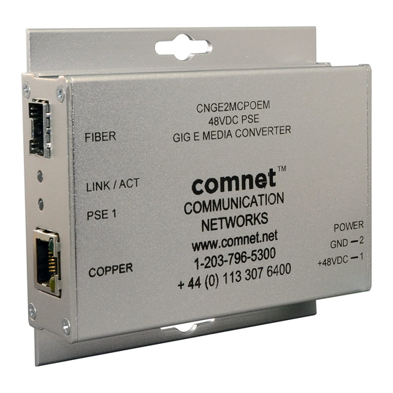
CNGE2MCPOEM
10/100/1000 MBPS 2 PORT MEDIA CONVERTER
WITH POWER OVER ETHERNET
The ComNet™ CNGE2MCPOEM Ethernet 2 port media converter is designed
to transmit and receive 10/100/1000 Mbps data over optical fiber through user
selectable SFP options. The CNGE2MCPOEM transmits and receives a single
channel of Ethernet data. As power sourcing equipment (PSE), it also supports
IEEE802.3at with up to 30 Watts of operating power to the remote powered
device (PD). It requires the ordering of sold-separately interchangeable SFP
modules for fiber type, distance and connectors. Its electrical interface will
Auto-Negotiate to a 10 Mbps, 100 Mbps or 1000 Mbps Ethernet rate without
any adjustments. The optical interface operates at a 1000 Mbps Ethernet
rate. The CNGE2MCPOEM is environmentally hardened to operate in extreme
temperatures.
LED indicators are provided for confirming equipment operating status. See
Figure 3 on Page 3 for LED indicator descriptions.
See Figures 1 – 4 for complete installation details.
The CNGE2MCPOEM operates as a standalone module. See Figure A on Page
4 for mounting instructions.
INS_CNGE2MCPOEM_REV–
06/21/11
PAGE 1
Advertisement

Related Manuals for Comnet CNGE2MCPOEM


Summary of Contents for Comnet CNGE2MCPOEM
- Page 1 LED indicators are provided for confirming equipment operating status. See Figure 3 on Page 3 for LED indicator descriptions. See Figures 1 – 4 for complete installation details. The CNGE2MCPOEM operates as a standalone module. See Figure A on Page 4 for mounting instructions. INS_CNGE2MCPOEM_REV–...
- Page 2 INSTALLATION AND OPERATION MANUAL CNGE2MCPOEM FIGURE 1 – CNGE2MCPOEM MEDIA CONVERTER OPTICAL FIBER DETERMINED BY SELECTION OF SFP MODULE CAT5e/6 BLACK BLACK WITH WHITE STRIPE FIGURE 2 – CNGE2MCPOEM MEDIA CONVERTER FRONT PANEL REAR PANEL NOTE: Remove Electrical Connector for Rack Mount Units INS_CNGE2MCPOEM_REV–...
-
Page 3: Installation And Operation Manual
INSTALLATION AND OPERATION MANUAL CNGE2MCPOEM FIGURE 3 – LED INDICATORS LINK/ACT PSE1 POWER GREEN Fiber interface linked Power is being Unit powered up (when lit or fl ashing) supplied by unit Fiber interface not Power not supplied Unit powered down linked. - Page 4 8 TURNBERRY PARK ROAD | GILDERSOME | MORLEY | LEEDS, UK LS27 7LE T: +44 (0)113 307 6400 | F: +44 (0)113 253 7462 | INFO-EUROPE@COMNET.NET INS_CNGE2MCPOEM_REV– 06/21/11 © 2011 Communications Networks Corporation. All Rights Reserved. “ComNet” and the “ComNet Logo” are registered trademarks of Communication Networks, LLC. PAGE 4...
Need help?
Do you have a question about the CNGE2MCPOEM and is the answer not in the manual?
Questions and answers