Table of Contents
Advertisement
Advertisement
Table of Contents

Subscribe to Our Youtube Channel
Related Manuals for Akerstroms SESAM 800 L15


Summary of Contents for Akerstroms SESAM 800 L15
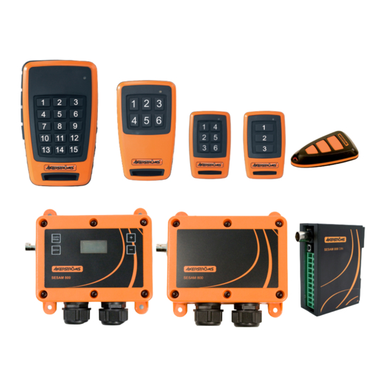
- Page 1 OPERATING MANUAL SESAM 800 L15, M6, S6, S3, K3, RXD, RX, RX DIN 941211-000 -D1...
-
Page 2: Table Of Contents
2 (36) Table of Contents Introduction _________________________________________ 4 Scope _____________________________________________ 4 Technical Specifications _______________________________ 5 Description of the System _____________________________ 7 Receivers ________________________________________________7 Transmitters ______________________________________________8 Description of the Receivers ___________________________ 9 Installation of the Receiver ____________________________ 12 Placement of the Receiver __________________________________12 Antenna Placement ________________________________________13 Connections on the Receiver (All Models) ______________________13 Indicators On the Receivers ___________________________ 14... - Page 3 3 (36) Sesam 800 RX DIN _______________________________________23 8.3.1 Basic Configuration ______________________________________________ 23 8.3.2 Advanced Configuration ___________________________________________ 23 8.3.3 Erasing All Transmitters in the Receiver SESAM 800 RX DIN ______________ 24 8.4 High Security Transmission Mode for RX and RXD _______________25 8.5 Memory Card (Only RXD) ___________________________________26 8.5.1 Copying Information from a Memory Card to a New Receiver ______________ 26 8.5.2 Copying Information from a Receiver to a Memory Card __________________ 27 Description of the Transmitters ________________________ 28 Indicators on the Transmitter _________________________________28 10 Replacing Batteries in the Transmitters _________________ 30 10.1 Replacing Batteries in Sesam K3 _____________________________30 10.2 Replacing Batteries in the Sesam 800 S3 & S6 __________________31...
-
Page 4: Introduction
Introduction 4 (36) Introduction This manual only covers the installation of the Sesam radio remote door opening system. The Sesam System is not a complete door opening system: it provides only the set of outputs that are driven according to the actions performed by the operator of the transmitter. -
Page 5: Technical Specifications
Technical Specifications 5 (36) Technical Specifications Tabell 1. Technical Specifications, Sesam 800 System Specifications Operating frequency: 869,8 MHz Channel separation: 25 kHz Power output: < 5 mW Functional sensitivity: <= -107 dBm BER 10-4 Transmission principle: GMSK, TDMA Operating Temperature: -25°C - +55°C Storage Temperature: -40°C - +85°C Specifications RX/RXD IP- class:... - Page 6 Technical Specifications 6 (36) Specifications K3 IP- class: IP65 Dimensions: 67x44x13 mm Weight: Battery type: 2 * CR 2025 Lithium cells Screw Size PH00 Specifications S3 IP- class: IP67 Dimensions: 75 x 46 x 22 mm Weight: Battery type: 2 * AAA/LR03 Alkaline Screw Size PH00 Specifications S6...
-
Page 7: Description Of The System
Description of the System 7 (36) Description of the System Receivers This document covers three receiver models. RX, RXD and RX DIN. RX and RXD can be ordered as 230 V AC or 12-24 V AC/DC. RX DIN only as 12-24 V AC/DC. Sesam 800 RX: •... -
Page 8: Transmitters
Description of the System 8 (36) Transmitters This document covers five transmitter models: Keyring K3: • Miniature 3 button transmitter. • Suitable for controlling 3 non-response time critical func tions. Small S3: • Small size 3 button transmitter. • Suitable for controlling 3 func tions. Small S6: •... -
Page 9: Description Of The Receivers
Description of the Receivers 9 (36) Description of the Receivers Figure 1. Sesam 800 RX 230 V AC model indicators, connections and jumper. 1. LED 1 Relay 1 status 2. LED 2 Relay 2 status 3. LED 3 Relay 3 status 4. LED 4 Power 5. LED 5 Squelch 6. LED 6 Status 7. LED 7 Learn 8. Power connection 230 V AC 9. Jumper J1 High Security Transmission Mode setting 10. Learn/Erase button 11. Connection to relay 1 12. Connection to relay 2 13. Connection to relay 3 10 11 12 13 14. - Page 10 Description of the Receivers 10 (36) Figure 3. Sesam 800 RXD Figure 4. Sesam 800 RXD 230 V AC model 12-24 V DC/AC model connections connections 1. Power connection, 1. Power connection 2. Connection to relay 1 2. Connection to relay 1 3. Connection to relay 2 3. Connection to relay 2 4. Connection to relay 3 4. Connection to relay 3 5. Antenna connector 5. Antenna connector Sesam 800 Operating Manual Document-ID: 941211-000 Version: D1...
- Page 11 Description of the Receivers 11 (36) Figure 6. Sesam 800 RX DIN model Figure 5. Sesam 800 RXD model display connections and buttons and buttons 1. Learn/Erase button 1. Learn/Erase button 2. Power connection, 2. Enter button 3. Connection to relay 1 3. Memory position up button 4. Connection to relay 2 4. Memory position down button 5. Connection to relay 3 5. Display 6. LED 5 Squelch LED 6 Status LED 7 Learn Sesam 800 Operating Manual Document-ID: 941211-000 Version: D1 Author: SH...
-
Page 12: Installation Of The Receiver
Installation of the Receiver 12 (36) Installation of the Receiver The permanent installation of the receiver must include fuses that protect the equipment and wiring from over current and short-circuit. In detail the power supply of the receiver and all relay contacts must be fused. All fuses are used as disconnecting devices. -
Page 13: Antenna Placement
Installation of the Receiver 13 (36) Antenna Placement Attach the supplied antenna to the antenna connector on the receiver. Note that the antenna must not be placed near metal objects such as wiring, tinroof, etc. If an antenna cable is needed, contact Åkerströms Björbo AB. Connections on the Receiver (All Models) The receiver is equipped with connections for relays, power and an external antenna (see fig. -
Page 14: Indicators On The Receivers
Indicators on the Receivers 14 (36) Indicators on the Receivers Sesam 800 RX The Sesam 800 RX model has seven LED indicators that is displaying system information (see fig. 1 for positions of the LEDs). The indications on the LEDs are as follows: LED 1, Relay 1 status: LED ON indicates that the relay is active. -
Page 15: Sesam 800 Rxd Model
Indicators on the Receivers 15 (36) Sesam 800 RXD Model The Sesam 800 RXD model has an integrated display that shows additional system relevant information (see fig. 5). At activation of a certain function, the transmitter memory position will be shown in the display window. -
Page 16: Configuration Of The Receiver
Configuration of the Receiver 16 (36) Configuration of the Receiver Sesam 800 RX Model 8.1.1 Basic Configuration Open the lid on the receiver (6 TX20 screws). Press the Learn/Erase button until LED 7 is ON. The Learn Mode will be active for 10 seconds (as long as LED 7 is ON). a. -
Page 17: Advanced Configuration
Configuration of the Receiver 17 (36) 8.1.2 Advanced Configuration This configuration allows the user to determine which button activates a specific relay. Open the lid on the receiver (6 TX20 screws). Press the Learn/Erase button until LED 7 is ON. The Learn Mode will be active for 10 seconds. -
Page 18: Sesam 800 Rxd Model
Configuration of the Receiver 18 (36) Sesam 800 RXD Model 8.2.1 Basic Configuration Press the Learn/Erase button. The display window shall show “L r n” followed by the memory position that the transmitter will be stored in. The right decimal on the display flashes as long as the Learn mode is active (10 seconds). - Page 19 Configuration of the Receiver 19 (36) To select what memory position to use (memory positions can be 1-500) press the Memory Position UP or Memory Position DOWN buttons (see fig. 5). The flashing left decimal on the display indicates whether the cho- sen memory position is already used.
-
Page 20: Erasing Transmitters In The Receiver Sesam 800 Rxd
Configuration of the Receiver 20 (36) 8.2.3 Erasing Transmitters in the Receiver SESAM 800 RXD Erasing individual transmitters Press the Learn/Erase button. The display shows “L r n” followed by the memory position that will be erased. This mode will be active for 10 seconds. Change what memory position to delete (1 to 500) by using “+” and “-” buttons. -
Page 21: Pin Lock In The Receiver
Configuration of the Receiver 21 (36) 8.2.5 PIN Lock in the Receiver The Sesam 800 RXD can be protected from unauthorized configuration by us- ing a 4-digit PIN-code. When a PIN-code is configured, all buttons on the receiver are locked except the button used to enter the code (Enter button). - Page 22 Configuration of the Receiver 22 (36) • When all 4 digits are entered correctly the display will show ‘PAS’ (passed) and the buttons on the receiver will be unlocked for 60 seconds. If the PIN is incorrect the display will show ‘Err’. •...
-
Page 23: Sesam 800 Rx Din
Configuration of the Receiver 23 (36) Sesam 800 RX DIN 8.3.1 Basic Configuration Open the lid on the receiver. Open the lid of the receiver by pressing the snap fits on the sides with a screwdriver or similar and pull apart the cover. Press the Learn/Erase button until LED 7 is ON. -
Page 24: Erasing All Transmitters In The Receiver Sesam 800 Rx Din
Configuration of the Receiver 24 (36) c. Press the Learn/Erase button three times in order to activate relay three (the status LED will flash three times). Press the button that shall be used for activating the selected relay in the receiver. -
Page 25: High Security Transmission Mode For Rx And Rxd
Configuration of the Receiver 25 (36) High Security Transmission Mode for RX and RXD The High Security Transmission Mode uses encrypted authentication to ensures that the receiver only replies to commands from transmitters stored in the mem- ory. This mode makes it difficult to scan and record messages that could, with the right technology, open doors without using an authentic coded transmitter. -
Page 26: Memory Card (Only Rxd)
Configuration of the Receiver 26 (36) Memory Card (Only RXD) In applications where many transmitter is used to control one single receiver the receiver can be equipped with a detachable memory card containing a backup of all configuration parameters. If a receiver needs replacement, the user only has to install a new receiver of the same type and insert the memory card in the new receiver in order to get the same functionality as in the old receiver. -
Page 27: Copying Information From A Receiver To A Memory Card
Configuration of the Receiver 27 (36) 8.5.2 Copying Information from a Receiver to a Memory Card Note that the memory card has to be empty before copying the receiver memory to the card. To remove information from a memory card, insert the card in a new receiver and erase all transmitters (see chap. 8.2). Power off the receiver. -
Page 28: Description Of The Transmitters
Description of the Transmitters 28 (36) Description of the Transmitters Indicators on the Transmitter Normal operation Quick flashing RED = sending message. Continuous GREEN = Relay activated in the receiver (Feedback information from receiver). Fault indications 3 long RED flashes = Battery depleted, transmitter can not send commands. Continuous RED after activating command = Low battery. - Page 29 2. Buttons 1-6 The Sesam 800 M6 6 button transmitter Figure 14. The Sesam 800 M6 transmitter indicators and buttons. 1. Status LED 2. Buttons 1-6 The Sesam 800 L15 15 button transmitter Figure 15. The Sesam 800 L15 transmitter indicators and buttons. 1. Status LED. 2. Buttons 1-15 Sesam 800 Operating Manual Document-ID: 941211-000 Version: D1...
-
Page 30: Replacing Batteries In The Transmitters
Replacing Batteries in the Transmitters 30 (36) Replacing Batteries in the Transmitters 10.1 Replacing Batteries in Sesam K3 If the Status LED on the transmitter indicates low battery, replace the batteries promptly. Before changing the batteries note that changing of batteries must take place in a clean environment free from static electricity. The batteries are changed as follows: Open the battery cover by unscrewing the 3 screws on the backside of the transmitter housing (see fig. -
Page 31: Replacing Batteries In The Sesam 800 S3 & S6
Replacing Batteries in the Transmitters 31 (36) 10.2 Replacing Batteries in the Sesam 800 S3 & S6 If the Status LED on the transmitter in- dicates low battery, replace the batteries promptly. Before changing the batteries note that changing of batteries must take place in a clean environment free from static electricity. -
Page 32: Replacing Batteries In Sesam 800 M6
Replacing Batteries in the Transmitters 32 (36) 10.3 Replacing Batteries in Sesam 800 M6 If the Status LED on the transmitter indicates low battery, replace the batteries promptly. Before changing the batteries note that changing of batteries must take place in a clean environment free from static electricity. The batteries are changed as follows: Figure 22. Battery cover and Open the battery cover by unscrewing... -
Page 33: Replacing Batteries In The Sesam 800 L15
Replacing Batteries in the Transmitters 33 (36) 10.4 Replacing Batteries in the Sesam 800 L15 If the Status LED on the transmitter indicates low battery, replace the batteries promptly. Before changing the batteries note that changing of batteries must take place in a clean environment free from static electricity. The batteries are changed as follows: Open the battery cover by unscrewing the 6 screws on the backside of the... -
Page 34: Error Codes
Error Codes 34 (36) Error Codes The Sesam 800 receivers can display a number of error codes. The error codes depends on the model of the receiver. 11.1 Error Codes, Sesam 800 RXD Tabell 2. Error codes Sesam 800 RXD Id already programmed. -
Page 35: Receiver Drill Measure For Rx And Rxd
Receiver Drill Measure for RX and RXD 35 (36) Receiver Drill Measure for RX and RXD 225 mm 120 mm 102 mm Figure 28. The receiver shall be attached with 4 mm screws that are suitable for the surrounding environment 12.1 Measure for RX DIN Figure 29. The DIN receiver measure Sesam 800 Operating Manual Document-ID: 941211-000 Version: D1 Author: SH... - Page 36 Åkerströms Björbo AB Box 7, SE-785 21 Gagnef, Sweden street Björbovägen 143 SE-785 45 Björbo, Sweden Phone +46 241 250 00 Fax +46 241 232 99 E-mail sales@akerstroms.com www.akerstroms.com © Åkerströms Björbo AB, 2013...
Need help?
Do you have a question about the SESAM 800 L15 and is the answer not in the manual?
Questions and answers