Akerstroms SESAM 800 MOBILE Operating Manual
Hide thumbs
Also See for SESAM 800 MOBILE:
- Manual (112 pages) ,
- Operating manual (28 pages) ,
- Operating manual (16 pages)

Subscribe to Our Youtube Channel
Related Manuals for Akerstroms SESAM 800 MOBILE


Summary of Contents for Akerstroms SESAM 800 MOBILE
- Page 1 OPERATING MANUAL SESAM 800 MOBILE CONFIGURABLE M6, RXM Original Instructions 947422-000 EN C3...
-
Page 2: Table Of Contents
2 (16) Table of Contents Introduction ________________________________________3 Scope _____________________________________________3 Service ____________________________________________3 Maintenance ________________________________________3 Technical Specifications _________________________________ 4 Short Description of the System _______________________5 Receiver __________________________________________________ 5 Transmitters _______________________________________________ 5 Description of the Receiver ___________________________6 Indications on the Receiver ___________________________________ 7 Installation of the Receiver ____________________________8 Mounting Steps ____________________________________________ 8 Description of the Transmitter ________________________ 11 Indications on the Transmitter ________________________________ 11... -
Page 3: Introduction
Introduction 3 (16) Introduction This manual only covers the installation of the Sesam radio remote system. The Sesam system is not a complete remote control system; it provides only the set of outputs that are driven according to the actions performed by the operator of the transmitter. -
Page 4: Technical Specifications
Technical Specifications 4 (16) Technical Specifications System Specifications Operating frequency band: 869 MHz, 12 channels Channel separation: 25 kHz Power output: ≤ 5 mW Functional sensitivity: Better than -107 dBm BER 10 Transmission principle: GMSK, TDMA Operating Temperature: -25°C - +55°C Storage Temperature: -40°C - +85°C Receiver specifications S800RXM... -
Page 5: Short Description Of The System
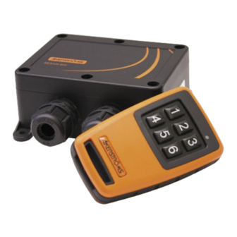
Short Description of the System 5 (16) Short Description of the System Receiver Main features: 6 solid state outputs. Each output is user configurable as either momentary or remaining. Waterproof (IP67). Type label position Transmitters M6 is a medium size 6- button transmitter. The transmitter comes in 2 different models, one with no button print and one with the button print 1...6. -
Page 6: Description Of The Receiver
Description of the Receiver 6 (16) Description of the Receiver Figure 1. Sesam 800 RXM model indicators, connections and jumper 1. Power LED 2. Ground 3. Positive (+) 12-24 V DC connector 4. Output power input 5. LED 5 6. LED 6 7. -
Page 7: Indications On The Receiver
Description of the Receiver 7 (16) Indications on the Receiver The Sesam 800 RXM model has LED indicators that indicate different param- eters (see Figure 1 for positions of the LEDs). The indications on the LEDs are as follows: Power LED ( Indicates whether the receiver is powered on or not. -
Page 8: Installation Of The Receiver
Installation of the Receiver 8 (16) Installation of the Receiver The permanent installation of the receiver must include fuses that protect the equipment and wiring from over current and short-circuit. The power supply to the receiver must be fused with 3A as close to the battery as possible. The cable must be of outer diameter 6-12 mm and each the power conductor at least 0.75mm . -
Page 9: Figure 3. Configuring Internal Supply Of Output Power
Installation of the Receiver 9 (16) Step 3 Connect wiring for output signals and power supply. Use cable ties to secure the wires and ensure that the wiring will not be affected by abrasion, heat and/ or exhausts. Connect 12-24 V DC (+) to position 3 and ground (-) to position 2 (see in Figure 1). -
Page 10: Figure 4. Numbering Of Outputs
Installation of the Receiver 10 (16) Step 4 Connect wiring for output signals and power supply. Use tie wraps to secure the wire and ensure that the wiring will not be affected by hot parts and/or exhausts. The power supply (+) to the receiver must be fused with a system adapted fuse as close to the battery/power supply as possible. -
Page 11: Description Of The Transmitter
Description of the Transmitter 11 (16) Description of the Transmitter Indicator LED Control buttons 1 2 3 4 5 6 Figure 5. The Sesam 800 M6 transmitter indicator and buttons Indications on the Transmitter Normal operation Quick flashing RED LED = Sending message but no feedback available from the receiver. -
Page 12: Replacing Batteries In The Transmitter
Replacing Batteries in the Transmitter 12 (16) Replacing Batteries in the Transmitter If the status indicator on the transmitter indicates low battery, replace the batter- ies promptly. Before changing the batteries note that changing of batteries must take place in a clean environment free from static electricity. The batteries are changed as follows: 1. -
Page 13: Pairing Receiver And Transmitter
Pairing Receiver and Transmitter 13 (16) Pairing Receiver and Transmitter If any part of the system has been replaced, the receiver and transmitter need to be paired together. Follow the steps below (please notice that this is for one transmitter see section 12.1 for more than one transmitter): 1. -
Page 14: Output Configuration
Output Configuration 14 (16) Output Configuration Each of the 6 outputs in the receiver can be configured as either momentary or remaining (latched) using a special configuration mode. Note! The transmitter/s and receiver must be paired before output configuration can be done, see chapter 12. Caution. -
Page 15: Receiver Drill Measures
Receiver Drill Measures 15 (16) Receiver Drill Measures 120 mm 102 mm Figure 11. Receiver drill measure The receiver shall be attached with 4 mm screws that are suitable for the sur- rounding environment Sesam 800 Configurable Version: C3 Document-ID: 947422-000 EN Author: SH... - Page 16 Åkerströms Björbo AB | Box 7, Björbovägen 143 | SE-786 97 Björbo, Sweden Phone +46 241 250 00 | frontoffice@akerstroms.se | www.akerstroms.se...
Need help?
Do you have a question about the SESAM 800 MOBILE and is the answer not in the manual?
Questions and answers