Sony XDS-PD1000 Operation Manual
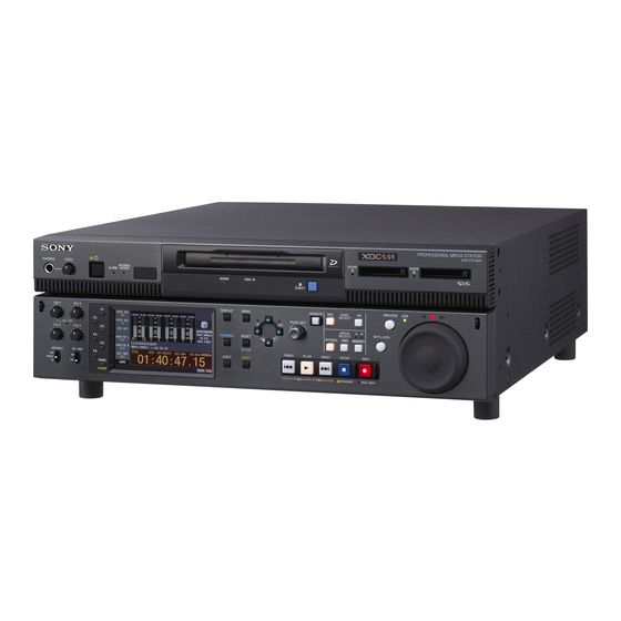
Professional media station
Hide thumbs
Also See for XDS-PD1000:
- Operation manual (169 pages) ,
- Operations & installation manual (60 pages) ,
- Brochure & specs (28 pages)

Related Manuals for Sony XDS-PD1000


Summary of Contents for Sony XDS-PD1000
- Page 1 PROFESSIONAL MEDIA STATION XDS-PD1000 XDS-PD2000 OPERATION MANUAL [English] 1st Edition...
- Page 2 3. Internal air ambient temperature of the rack WARNING When this product is installed in a rack, please make sure To reduce the risk of fire or electric shock, that the internal air ambient temperature of the rack is within the specified limit of this product.
- Page 3 (commercial and light industrial), E3 (urban outdoors), E4 Dette merket er plassert på oversiden av driverenheten. (controlled EMC environment, ex. TV studio). The manufacturer of this product is Sony Corporation, 1-7-1 CAUTION Konan, Minato-ku, Tokyo, Japan. The use of optical instruments with this product will increase eye hazard.
-
Page 4: Table Of Contents
Front Panel Tilt Mechanism ............30 Connections and Settings ............31 Connections for using XDCAM Browser or a nonlinear editor that is not a Sony product ................31 Connections for cut editing ..............32 Synchronization Reference Signals..........36 Setting System Frequency............37 Setting Time Data ................ - Page 5 Notes on handling ................44 Write-protecting discs................44 Loading and unloading a disc .............. 44 Formatting a disc ................. 45 Handling SxS Memory Cards ............45 About SxS memory cards ..............45 Inserting/removing an SxS memory card ..........46 Switching between SxS memory cards..........47 Chapter 4 Recording, Playback and Copying Recording..................
- Page 6 Formatting (initializing) discs ............. 66 Finalizing discs..................66 Chapter 6 File Operations Overview..................67 Directory structure................67 File operation restrictions ..............67 FTP File Operations............... 69 Making FTP connections..............69 Command list ..................69 CIFS File Operations ..............73 Making CIFS connections ..............73 Chapter 7 Menus Menu System Configuration ............
- Page 7 About DVB-ASI Input/Output (When the Optional PDBK-202 Is Used)..................111 Using UMID Data................113 Correspondence between Setting Items of the HKDV-900 and Setup Menu of This Unit............114 Trademarks and Licenses ............115 MPEG-4 visual patent portfolio license ..........115 MPEG-2 video patent portfolio license ..........
-
Page 8: Chapter 1 Overview
Features HDDs for internal storage Long recording times The XDS-PD1000/PD2000 is a full-HD (1920 × 1080 and This unit is equipped with HDDs for internal storage. 1280 × 720) hybrid media deck that can use an internal These HDDs provide 1 terabyte (TB) of data storage,... - Page 9 SD signals and then output as SD-SDI or composite signals. This allows 1) MPEG HD is a registered trademark of Sony Corporation. you to use this unit for editing and program output in an SD 2) SDI recording only supported for 35 Mbps, and playback only supported for 25 Mbps and 18 Mbps.
- Page 10 - RS-422A (D-sub 9-pin) (2) from –2 to +2 times normal speed. Shuttle mode supports (In addition to the Sony 9-pin VTR protocol, this unit high-speed searches up to a maximum of ±20 times normal supports the Video Disk Control Protocol (VDCP).) speed.
-
Page 11: System Configurations
System Configurations The figure below shows devices and media that can be • Satellite news gathering (SNG) system (see page 12) used with this unit. • Ingesting/editing system (see page 12) You can use this unit and these devices to configure the •... -
Page 12: Satellite News Gathering (Sng) System
Satellite news gathering (SNG) system The following figure shows an example of SNG system in which this unit is used as both server and backup recorder. On the satellite truck Computer (installed with XDCAM Browser) DVB-ASI TS signal DVB-ASI This unit This unit TS signal SDI signal... -
Page 13: Live Production System
Live production system The following figure shows an example of sports relay or live recording system in which this unit is used as both editing feeder and backup recorder. Slow-motion/replay controller RS422 (VDCP) This unit Monitor Slow-motion/ replay video Live video (SID signal) SDI signal Camcorder Global Ethernet... -
Page 14: Chapter 2 Names And Functions Of Parts
Names and Functions of Parts Chapter Front Panel The names and symbols of buttons and knobs on the front Orange: Function when the button is operated with the panel are color coded according to function. SHIFT button held down. White: Function when the button or knob is operated Blue: Function related to thumbnail operations. - Page 15 c On/standby (1) button and indicator 1 Port and media selection section When the main power switch on the rear panel is in the on This unit has a recording port and a playback port. You can position, this switches the unit between the operating state control these ports independently by selecting one of them (the indicator is lit green) and the standby state (the with the REC PORT or PB PORT button.
- Page 16 e MEMORY button a Memory card slots This button selects an SxS memory card as the operation These two slots (A and B) can receive SxS memory cards target media. (see page 46). f Slot selection lamps b Eject buttons These light to indicate the selected memory card slot.
-
Page 17: Display Button
To set the audio level of each port separately, adjust one or Note the other by using external audio equipment connected to It is not possible to adjust the audio levels of the recording a REMOTE (9P) connector (1 or 2). and playback ports simultaneously. - Page 18 g COPY button b PLAY button Displays the Clip Copy screen. (see page 55). To start playback, press this button, turning it on. h RESET/RETURN button c NEXT button Functions as the RESET button or the RETURN button. Press this button, turning it on, to jump to the next clip and RESET button: Resets counters or the setting values of show the first frame.
- Page 19 7 Shuttle/jog/variable-speed playback • In variable-speed mode, you can make fine adjustments to the playback speed over the range from –2 to +2 times control section normal speed, according to the angular position of the dial. There is a detent at the center position, for still image playback.
-
Page 20: Display Screen
Display screen Basic operation screen 1 Function menu 2 Audio input display/audio level meters 3 System information 4 Media status display 5 Recording or playback format 6 Clip information 7 Recording or chase play display 8 Time data display area 9 Status display area a Function menu Display... - Page 21 c System information SD-SDI: SD-SDI video input SG: Test video signal from the internal signal generator DVB-ASI : DVB-ASI TS signal A Reference signal 1) When the maintenance menu item M22: OPTION SETTING >DVB- B Video input display ASI is set to “ON” with the optional PDBK-202 being installed (see page 92).
- Page 22 A Remaining media capacity for recording or playback: Displays the amount of remaining capacity Codec for recording or playback on the media. Video format B REC RUN/FREE RUN: Displays the timecode run mode. The run mode is set with RUN MODE on page System frequency P4 TC of the function menu (see page 43).
- Page 23 A Error, warning, and alarm messages: Messages about operations and the status of the unit appear here. The seriousness of the message is indicated by the color, as follows. Red: Error message (flashing) Orange: Warning message White: Alarm message B Delete icon: Flashes while a clip deletion is being executed.
-
Page 24: Rear Panel
Rear Panel 2 DVB-ASI OUTPUT connector 3 HDMI OUTPUT connector 4 REF. VIDEO INPUT connectors 2 Timecode input/output section (see page 26) 1 PCIe expansion slot 5 Redundant power supply unit installation section 1 HD/SD-SDI signal input/output 3 Power supply section section (see page 25) (see page 26) qd COMPOSITE OUTPUT 1, 2 (MONITOR) connectors... - Page 25 REMOTE (9P) 2 connector: Controls the playback port. (SUPER) connectors Connect a VTR or a controller that supports the RS-422A Sony 9-pin VTR protocol (see page 32). h VIDEO CONTROL connector (D-sub-9-pin) 4 HD-SDI MONITOR OUTPUT connector Connect an HKDV-900 video control unit.
- Page 26 b HD-SDI OUTPUT 1, 2 (SUPER) (HD-SDI signal e SD-SDI (SD-SDI signal) MONITOR OUTPUT output 1, 2 (superimpose)) connectors (BNC type) connector (BNC type) These output HD-SDI format video/audio playback This outputs SD-SDI format video/audio signals. Output signals. signals are E-E signals or playback signals, according to You can superimpose timecodes or error messages on the the setting of the REC PORT and PB PORT buttons on the output of the 2 (SUPER) connector with the setting for...
- Page 27 a ANALOG AUDIO INPUT 1, 2 connectors (XLR 3- (showing that this unit is in the standby state), and then press the main power switch to the off side. pin, female) These input analog audio signals. b AC power input connector (-) With A1 INPUT to A4 INPUT on page P1 INPUT (see Connect to an AC power supply with the power cord (not page 42) and A5 INPUT to A8 INPUT on page P2 INPUT...
-
Page 28: Chapter 3 Preparations
Preparations Chapter Supplying Power Initial Setup Connect the AC power input connector to an AC power This unit is shipped with the area of use, system frequency, source using the specified AC power cord. To supply and current date and time still unset. power, set the main power switch on the rear panel to on, Therefore, you need to make initial setup settings before and then press the on/standby (1) button on the front panel... - Page 29 Note The time zone is reset to the factory default when you execute the maintenance menu item M49: RESET ALL SETUP. You will need to set it again. The date and time are not reset. Turn the PUSH SET knob to select the area of use. Display UC (for regions outside Japan) or J (for Japan), and then press the SET function button (F5).
-
Page 30: Front Panel Tilt Mechanism
Note Front Panel Tilt The angle cannot be fixed if you pull the front panel past Mechanism position 3 all the way out to the return position. To fix the front panel, return it to position 0 and then pull it out to the desired angle. -
Page 31: Connections And Settings
You can also access to this unit from a nonlinear editor that is not a Sony product via FTP/CIFS, and use this unit as a material server. For an overview and installation of the XDCAM Browser, access the Sony website closest to your area. -
Page 32: Connections For Cut Editing
Connections for cut editing The following figure shows a cut editing system When making the connections, also refer to the manuals comprising this unit as a player. provided with the equipment to be connected. When using an editing control unit BVE-700/700A The following figure shows a cut editing system unit as a recorder, and a BVE-700/700A as an editing... - Page 33 VTR constant 59.94i/59.94P/29.97P 50i/50P/25P 23.98P a) XDS-PD1000: B1, XDS-PD2000: B2 Using the RM-280 Editing Controller The following figure shows a cut editing system unit as a recorder, and an RM-280 as an editing control comprising this unit as a player, an HDW-M2000/M2000P unit.
- Page 34 Settings on each unit Device Settings HDW-M2000/M2000P (recorder) • REMOTE 1 (9P) button: Lit • REF.VIDEO INPUT connector 75 Ω termination switch: OFF • Audio selection function switching button INPUT button: HDSDI • Function menu HOME >F1 (VID. IN): SDI •...
- Page 35 Settings on each unit Device Settings HDW-M2000/M2000P (recorder) REMOTE 1 (9P) button: Unlit This unit (player) • Setup menu item 208 PROTOCOL FOR REMOTE(9P): VTR • REMOTE button (for playback port): Lit For details of HDW-M2000/M2000P settings, refer to the HDW-M2000/M2000P Operation Manual.
-
Page 36: Synchronization Reference Signals
Synchronization Reference Signals The synchronization reference signal generator of this unit setting of OUT REF on the HOME page of the function synchronizes to a reference signal input to the REF. menu, and on the type of the selected input signal. Video VIDEO INPUT connector or to a video input signal. -
Page 37: Setting System Frequency
Setting System Setting Time Data Frequency Setting timecode This unit can record and play back video at the system There are the following four ways of recording timecode: frequencies of 1080/59.94i, 50i, 29.97P, 25P, and 23.98P Internal Preset mode: This records the output of the or 720/59.94P and 50P. - Page 38 Setting an initial timecode value To record timecode synchronized to the station’s reference time Press the CNTR SEL function button on the HOME On page P4 TC of the function menu, set TCG to “SYS”. page of the function menu, and select TC. This selects recording of timecode synchronized to a broadcast station reference timecode signal input to the Press the TCG SET function button (F3).
-
Page 39: Setting User Bits
To check the synchronization to the external Superimposed Text signal Press the REC PORT button to select the recording port. Information Check that the timecode value shown in the time data display coincides with the external timecode value. The video signal output from the following connectors on To record external timecode directly this unit contains superimposed text information, (External Preset) - Page 40 a Type of time data Display Operation mode Display Meaning Block A Block B Counter data PREV xxx Cuing up to the first frame of the current clip. TC reader timecode F.FWD Fast forward search TC reader user bits data F.REV Fast reverse search TCR.
-
Page 41: Basic Operations Of The Function Menu
To change the setting of a function menu Basic Operations of the item Use the function buttons. Function Menu To select the value of the setting item Press the function button to the left of each setting item to The function menu provides access to frequently used change the value of the item. - Page 42 Item Setting Item Setting F5: MONITR R Selects the channel to monitor as the right F5: A3 INPUT Selects the audio input signal to assign to monitor channel. audio channel 3. CH1, CH2, CH3, CH4, CH5, CH6, CH7, SDI: Audio signal embedded into SDI signal ANALOG1: Input signal to the ANALOG CH1/2, CH3/4, CH5/6, CH7/8 (MIX) AUDIO INPUT 1 connector...
- Page 43 P3 AUDIO page Item Setting F2: PRST/RGN Selects the following for the internal Item Setting timecode generator. F1: A5 VOL Sets the volume of audio channel 5. PRESET: Presets an initial value for the The volume can be adjusted within the timecode generated by the internal range from –200 to 0 to +200 (–∞...
-
Page 44: Handling Discs
• Store cartridges in their cases. • PFD128QLW (capacity 128 GB) Care of the discs 1) Professional Disc is a trademark of Sony Corporation. • Remove dust and dirt on the outside of a cartridge using a soft dry cloth. -
Page 45: Formatting A Disc
About SxS memory cards SxS memory cards that can be used with this unit To load Use the following Sony SxS memory cards (SxS PRO or Insert a disc face up. SxS-1) with this unit. The disc is drawn in. -
Page 46: Inserting/Removing An Sxs Memory Card
Memory card slots lock the cases securely. MEMORY ACCESS A/B lamps • Guard against accidents and inadvertent data loss by backing up the data stored on SxS memory cards. Sony MEMORY button Eject buttons cannot be responsible for any consequences of damage to or loss of data stored on SxS memory cards. -
Page 47: Switching Between Sxs Memory Cards
Status indications by the MEMORY ACCESS A/B Switching between SxS memory lamps cards Card slots A and B are accompanied by the respective lamps to indicate their statuses. When SxS memory cards are loaded in both memory card Lamp Slot statuses slots A and B, press the MEMORY button to select the Lights in orange Accessing the loaded SxS memory card... -
Page 48: Chapter 4 Recording, Playback And Copying
Recording, Playback and Copying Chapter For the available recording time of each media, see Recording “Recording and playback time” under “Specifications” (see page 108). This section describes video and audio recording on the unit. See page 41 “Basic Operations of the Function Menu” for more information. -
Page 49: Mixed Recording Of Clips In Different Formats On The Same Disc
In the case of simultaneous recording, this unit enters • When recording to the internal storage becomes a stop mode after copy from the internal storage to the impossible, the recording to the Professional Disc also Professional Disc. stops. To stop only the recording to the Professional Disc To adjust the audio recording levels during simultaneous recording Press the COPY button and then press the RESET... -
Page 50: Playback
Frame frequency System frequency Playback 50 Hz This section describes playback of video and audio on the 23.98 Hz 23.98P unit. Before starting playback, make the following settings and Notes adjustments. • When the unit is in a mode that calls for playback across Selection of time data to display: Select with CNTR SEL clips that were recorded in different recording formats, on HOME page of the function menu. -
Page 51: Selecting A Clip Or An Edl
• In the case of quad-layer WO discs, the playback Selecting a clip or an EDL position is not saved. After recording The unit stops at the position where recording ended. DISPLAY button To play back a clip, press the PREV button to move to the start frame of any clip or press the PREV button with the PLAY button held down to move to any position. - Page 52 Normal playback Press the SHTL/JOG button or VAR/JOG button, turning it on. Turn the shuttle/jog dial in the desired direction, at the speed corresponding to the desired playback speed. Playback in jog mode starts. STOP button PREV button NEXT button To stop playback in jog mode, stop turning the shuttle/ jog dial.
-
Page 53: Playback Operations Using Thumbnails
Playback operations using Note thumbnails Video and audio become discontinuous if you conduct shuttle playback of a clip that does not have proxy AV data. Playback operations that you can perform with thumbnails include searching for clips, displaying clip information, To alternate between normal-speed playback and and locking and deleting clip. -
Page 54: Copying
• When an MXF clip on SxS memory card, Professional Copying Disc or internal storage is copied, the UMID data of the copy source clip is maintained intact. If the copy destination media contains a clip with same UMID data as the clip selected as copy source, it is not possible to Overview copy the selected clip. - Page 55 To copy part of the clip selected in step 4: Proceed When two SxS memory cards are loaded Press the MEMORY button to switch between the to step 7 without pressing the SOURCE function copy target cards (A/B). button (F1). Do one of the following to select the clip to copy.
-
Page 56: Chase Copy
To perform deletion, insert the desired memory card An IN/OUT setting window appears in the bottom into the ExpressCard slot of a computer or into an SxS right corner of the display. memory card reader connected to a computer, and use The IN point timecode is displayed in the IN/OUT XDCAM Browser or other appropriate application setting window, and the IN indicator lights. - Page 57 The Clip Copy screen appears. Press the START function button (F5). The copy processing for the selected clip starts. The copy icon lights in the status display area. Press the DISC button. The Clip Copy screen displays the progress of copy processing.
-
Page 58: Chapter 5 Operations In Clip List Screens
Operations in Clip List Screens Chapter Overview Use clip list screens to search for scenes, play scenes found You can switch between the details view and the by searching, select clips to copy, and perform other thumbnails view of clip list screens. operations related to clips. -
Page 59: Information And Controls In Clip List Screens
d Clip number/total number of clips Information and controls in clip list Displays the total number of clips (including EDLs) on the screens selected media, and the number of the selected clip (or EDL). Thumbnails view e Scrollbar When not all of the thumbnails can be displayed in the thumbnail display area, the position of the slider shows the relative position of the currently displayed clips, and the length of the slider shows the relative length of currently... - Page 60 n Recording or playback status icon Details view When the recording media is the internal storage, an icon appears to indicate the recording or playback status ( : recording, : playing, : chase play). 1) “Playing” means that the clip is open (the file is open) because the clip has been selected, in a clip list screen or elsewhere.
-
Page 61: Clip Menu
f Unplayable icon/playback or recording status icon d Thumbnail number/total number of thumbnails An unplayable icon appears to indicate that the clip cannot Displays the total number of thumbnails of the divided clip be played (or EDL), for example because the system and the number of the currently selected thumbnail. -
Page 62: Clip F Menu
Item Sub-item Function Item Function Format Disc – Formats (initializes) a F2: CLIP Displays the Clip Properties screen. recorded Professional PROPERTY Disc (when the F3: FOLDER When the currently selected media is a currently selected Professional Disc, selects the folder media is Professional (CLIP, UserData >XDROOT, UserData>... -
Page 63: Clip Operations
To play the clip you have found Clip Operations Select the clip, and then press the PLAY button. To search through a clip in the expand Note thumbnail screen The following operations target only clips on internal The expand function allows you to divide a clip selected in storage/Professional Disc. -
Page 64: Setting Clip Flags
This step is not needed if you lock all clips. Setting clip flags Display the Clip Menu. You can set three types of clip flags (OK/NG/KP(KEEP)) for selected clips. Setting these flags in each clip that you Select Lock Unlock Clips. record makes it easy for editors and other colleagues to find and select the clips that they need. -
Page 65: Copying Clips
Select Delete Clips. To set another frame as the index picture frame Select “CANCEL” and press the PUSH SET knob, The Delete Clips screen appears. turning the confirmation box off. Start again from step 1. When you switch the display to the clip list screen, the newly set index picture is displayed as the thumbnail. -
Page 66: Disc Operations
Finalizing discs Disc Operations You can finalize write-once type Professional Discs. The Clip Menu allows you to format (initialize) and Notes finalize a Professional Disc. • You cannot write additional data to finalized discs. • Finalized discs cannot be finalized again. Formatting (initializing) discs Insert the disc you want to finalize into the disc slot. -
Page 67: Chapter 6 File Operations
File Operations Chapter Overview A remote computer can be connected to this unit and used to operate on recorded data which has been saved in data files, such as video and audio data files. To perform file operations, use either of the following methods to interconnect this unit and a computer. - Page 68 INTERNAL directory (xds style)/root directory (xdcam style) File name Content Operations Read Write Rename Create Delete DISCMETA.XML Contains metadata to indicate the internal storage properties. MEDIAPRO.XML Contains a list of material on the internal storage, basic properties, related information, and information about access methods.
-
Page 69: Ftp File Operations
For details, see “To check the assigned IP address” (page 96). The password is set to the model name (“xds-pd1000” or “xds-pd2000”) when the unit is shipped from the 1) This unit is able to acquire an IP address automatically from a DHCP server. - Page 70 TYPE Notes Specifies the type of data to be transferred. • To execute FTP commands, you must install application Command syntax: TYPE <SP> <type-code (options software such as XDCAM Browser on your computer. delimited by <SP>)> <CRLF> • The commands supported by application software vary. •...
- Page 71 The following data is transferred, depending on whether Notes <path-name> specifies a directory or file. • For *.MXF files or *E01.SMI files, the UMID of the • Directory specified: A list of the files in the specified copy source file is not saved. However, it is saved if an directory •...
- Page 72 - CODEC type Moves to a directory as follows, depending on whether a - Frame rate directory is specified with <path-name>. - Number of audio channels • Directory specified: To the specified directory - Duration • No specification: To the root directory - UMID Input example: CWD Clip •...
-
Page 73: Cifs File Operations
OK. end of the file). Input example: SITE REPFL “Clip/sakura 0001.MXF” 5 150 The password is set to the model name (“xds-pd1000” Transfer sakura 0001.MXF. For the body, or “xds-pd2000”) when the unit is shipped from the however, data from sixth frame through 150th factory. -
Page 74: Chapter 7 Menus
Menus Chapter Menu System Setup Menu Configuration The setup menu system of this unit comprises the basic setup menu and extended setup menu. The settings for this unit use the following menus. Basic menu Setup menu This menu is used to make settings relating, for example, The setup menu system of this unit comprises the basic to the following. -
Page 75: Items In The Basic Menu
Item group Function Refer to Item group Function Refer to Items Settings relating to control page 79 Items Settings relating to the page 82 100 to 199 panels 650 to 699 metadata and UMID Items Settings relating to the remote page 79 Items Settings relating to video... - Page 76 Item number Item name Settings LOCAL FUNCTION ENABLE Determine which recording and playback control buttons on the front panel are enabled when this unit is controlled from external equipment via a REMOTE (9P) connector. all disable [dis]: All buttons and switches are disabled. stop &...
-
Page 77: Basic Menu Operations
Item number Item name Settings RECALL SETUP BANK-1 Set to “on” to recall menu bank 1 to replace the current menu settings. RECALL SETUP BANK-2 Set to “on” to recall menu bank 2 to replace the current menu settings. RECALL SETUP BANK-3 Set to “on”... - Page 78 sure to press the SAVE function button (F5) after Current setting making the settings. To return menu settings to their factory default settings After changing menu settings, use the following procedure to return the settings to their factory default settings (setting initialization).
-
Page 79: Items In The Extended Menu
CIFS and handled on the network. Note When using a nonlinear editor that is not a Sony product, please contact the maker to confirm whether it is possible or not to receive clips output by the chase output function using MXF V1.3 format. - Page 80 Menu items in the 200s, relating to the remote control interface Item number Item name Settings VIDEO REMOTE CONTROL Select the method used to control the internal digital video processor and to make related settings. SELECT menu: Use the setup menu to change settings. remote (down converter) [dc]: Control the down-converter from an HKDV-900 or another device connected to the VIDEO CONTROL connector.
- Page 81 Menu items in the 600s, relating to the timecode, metadata, and UMID Item number Item name Settings VITC POSITION In 59.94i/59.94P/ Select the line into which to insert VITC signals (SD output) SEL-2 29.97P mode 12H to 18H to 20H: Any line from line 12 through line 20. Notes •...
- Page 82 Menu items in the 600s, relating to the timecode, metadata, and UMID Item number Item name Settings TIME CODE FOR VDCP CONTROL Make a setting for timecode generated when the REC INIT command or CUE WITH DATA command is executed from a VDCP-compliant controller.
- Page 83 Menu items in the 700s, relating to video control Item number Item name Settings BLANK LINE SELECT Switch blanking of the video output signal on or off for individual lines in the vertical blanking interval. Sub-item The Y/C signal and odd/even fields are blanked simultaneously. ALL LINE - - -: Specify the blanking for each line separately.
- Page 84 Menu items in the 700s, relating to video control Item number Item name Settings VIDEO SETUP REFERENCE Set the video setup amount to be added to the composite output signal (in 59.94i/59.94P/29.97P mode only). Sub-item OUTPUT LEVEL In 59.94i/59.94P/ Add the setup level selected by this item to the output signal. 29.97P mode 0.0%, 7.5% (UC)
- Page 85 Menu items in the 700s, relating to video control Item number Item name Settings WIDE MODE Specify whether to record and play back with the addition of wide picture information. Sub-item INPUT Select whether to save wide picture information when recording. auto: Automatically save wide picture information when it is detected in the selected input video signal.
- Page 86 Menu items in the 800s, relating to audio control Item number Item name Settings AUDIO OUTPUT PHASE Set the output timing of digital audio playback signals (HD-SDI, SDI, AES/EBU only) as a hexadecimal value, with 80 as a reference position. Output timing is earlier for values smaller than 80 and later for values greater than 80.
- Page 87 Menu items in the 900s, relating to digital process Item number Item name Settings Select the resolution of the video output from the HDMI OUTPUT HDMI OUTPUT SELECT connector. 1080i, 480i, 480P (59.94i, 29.97P mode) 1080i, 576i, 576P (50i, 25P mode) 720P, 480i, 480P (59.94P mode) Sets the parameters for DVB-ASI output, and specifies the number of the a) b)
- Page 88 Menu items in the 900s, relating to digital process Item number Item name Settings PID(VIDEO) Changes the VIDEO packet PID value for DVB-ASI output. 30 to 810 to 1FFE: Set PID value (as a hexadecimal value). You can set the value over the range from 30 to 1FFE in 1 units (or 20 units, when the SHIFT button is held down).
- Page 89 Menu items in the 900s, relating to digital process Item number Item name Settings LEVEL DEPEND THRESHOLD Adjust the down-converter image enhancer. Set the luminance range for (DC) edge enhancement. 0 to 8 to FH H DETAIL FREQUENCY (DC) Adjust the down-converter image enhancer. Set the central frequency for edge enhancement.
-
Page 90: Extended Menu Operations
Menu items in the 900s, relating to digital process Item number Item name Settings IMAGE ENHANCER (INPUT UP Set up the operation of the up converter image enhancer for SD input, separately from the settings for playback (menu items 950 to 959). CONVERTER) Sub-item pb: While SD signals are input, make the behavior of the image... - Page 91 Turn the PUSH SET knob to select “M4 SETUP MAINTENANCE”, then press the PUSH SET knob or the SELECT function button (F2). The sub-items of M4: SETUP MAINTENANCE appears. Turn the PUSH SET knob to select “M40 EXTENDED MENU”, then press the PUSH SET knob or the SELECT function button (F2).
-
Page 92: Maintenance Menu
Maintenance Menu Items in the maintenance menu The following tables show the items in the maintenance • The underlined values are the factory defaults. menu. • The values in the “Setting” column are the values that Refer to the Maintenance Manual for information about appear in settings screens. - Page 93 M3: OTHERS: Other setting items Item Setting M37: AUDIO M370: HEAD ROOM Select the audio reference level (headroom). CONFIG –20dB, –18dB, –16dB, –12dB, EBUL Note EBUL can be selected only when the system frequency is 50i/25P. M371: DATA LEN Select the audio channel configuration for IMX recording. 16bit x 8ch [16x8]: 16-bit, 8-channel configuration 24bit x 4ch [24x4]: 24-bit, 4-channel configuration M372: NON-AUDIO...
- Page 94 M3: OTHERS: Other setting items Item Setting M3B: VANC RX M3B0: VANC RX For setting HD-SDI VANC data input parameters PARAMETER PACKET Notes • In 59.94i, 50i, 29.97P or 25P mode, selecting the line also selects the corresponding line in the second field (for example, if line 9 is selected, line 572 is also selected for VANC packet reception).
- Page 95 M5: NETWORK: Items relating to network settings Item Setting M51: IP ADDRESS Set the IP address of this unit. 192.168.001.010 Notes • IP address cannot be set when DHCP is set to “ENABLE”. • To check the automatically acquired IP address of this unit, close the maintenance menu and then open it again.
-
Page 96: Maintenance Menu Operations
Use the PUSH SET knob or the V and v buttons to Maintenance menu operations select the required item, then press the PUSH SET knob or the SELECT function button (F2). This section describes the indications in the maintenance menu and how to change the settings. The sub-items of the selected item appears. - Page 97 Contact your network administrator if you have any Note questions about the proper settings for these items. If the IP address cannot be assigned, this is shown as “000.000.000.000.” In this case, consult the network Select maintenance menu item M5: NETWORK administrator.
-
Page 98: Appendix
In the event of operating problems If you should experience problems with the unit, contact Condensation your Sony service or sales representative. If you move the unit from a very cold place to a warm Use and storage locations place, or use it in a damp location, condensation may form on the optical pickup. -
Page 99: Precautions For Products With Built-In Hdd
HDD can occur. HDD replacement • When transporting the unit, use the specified packing Contact your Sony service or sales representative about material. When transporting on a dolly or similar, use a periodic replacement of the HDD. -
Page 100: Periodic Maintenance
Press the RETURN function button (F1) to return to the maintenance. setup menu. For periodic maintenance, contact your Sony service or Press the EXIT function button (F6) to return to the screen sales representative. that was displayed before you entered the setup menu. -
Page 101: Troubleshooting
Example alarm in video monitor screen When an alarm is displayed, remove the alarm cause by following the action to take. If the alarm display does not disappear, contact your Sony service or sales representative. When the unit is powered on... - Page 102 Alarm message in status Alarm message in video monitor screen Description/action display area SSD detect OPTIONAL SSD HAS BEEN DETECTED. An optional SSD has been detected. PLEASE CHECK AND SET Set the maintenance menu item D11: RAID. MAINTENANCE MENU ITEM D11. When a memory card is inserted Alarm message in status Alarm message in video monitor screen Description/action...
- Page 103 Alarm message in status Alarm message in video monitor screen Description/action display area DISC frequency mismatch! RECORDING OR PLAYBACK IS NOT This appears when the system frequency setting of POSSIBLE. SYSTEM SETTINGS this unit and the system frequency of the inserted DIFFERENT FROM DISC.
- Page 104 Alarm message in status Description/action display area STOP ONCE! This appears when an attempt is made to change media during recording or playback. Stop the recording or playback and try the operation again. Exit THUMBNAIL mode! This appears when an attempt is made to change media while the clip list screen is displayed. Switch to the basic operation screen or the video monitor screen and try the operation again.
- Page 105 During playback operations Alarm message in status Alarm message in video monitor screen Description/action display area ILL. PLAY! ILLEGAL PLAYBACK. Normal playback is not possible. MEM. Empty! MEMORY EMPTY !! Playback is not possible because a buffer underflow has occurred in the playback buffer memory. This Clip cannot be Played –...
- Page 106 Alarm message in status Alarm message in video monitor screen Description/action display area FAN(1/2) Error FAN(1/2) ERROR. Contact your Sony service or sales representative. Note FAN(1/2) Warning FAN(1/2) WARNING. The unit will not stop operating, but if you continue to DC Power Warning DC POWER STATUS IS NOT NORMAL.
-
Page 107: Error Messages
Other alarms Alarm message in status Alarm message in video monitor screen Description/action display area Turn off/on POWER!! SYSTEM CONFIGURATION WAS The system frequency was changed. CHANGED. Power off this unit and then power it on again. PLEASE TURN OFF/ON POWER. Turn off/on POWER!! MENU CONFIG WAS CHANGED. -
Page 108: Specifications
Mass XDS-PD1000: 17 kg (37 lb. 7.7 oz.) Specifications XDS-PD2000: 16 kg (35 lb. 4.4 oz.) Power requirements 90 V to 264 V AC, 47 Hz to 63 Hz Power consumption General XDS-PD1000: 190 W External dimensions (w/h/d, excluding projections) - Page 109 Multiple SD/HD codec SD-SDI input: complying with SMPTE- When recording 259M SD IMX 50 Mbps, and DVCAM HD-SDI input: complying with SMPTE- HD MPEG HD422, and MPEG HD 292M DVB-ASI TS input When playing back 1) When the optional PDBK-202 is installed. SD IMX 30/40/50 Mbps, and DVCAM Analog video inputs (MPEG HD LP supports only 1080i,...
- Page 110 (1 on front panel, 4 on rear panel) PCIe expansion slot × 8 slot (25 W) (2) Media drives Internal storage XDS-PD1000: Three units of 500 GB HDD (Data: 2 HDDs; Fault tolerance: 1 HDD) XDS-PD2000: Two units of 256 GB SSD...
-
Page 111: About Dvb-Asi Input/Output (When The Optional Pdbk-202 Is Used)
DVB-ASI TS signals via OF ANY TYPE. this connector. • Always verify that the unit is operating properly before use. SONY WILL NOT BE LIABLE FOR DAMAGES OF ANY KIND INCLUDING, BUT Note NOT LIMITED TO, COMPENSATION OR... - Page 112 Menu settings Setting the number of audio output channels for DVB- ASI TS signals: Setup menu item 831 TS OUT AUDIO MODE Switching DVB-ASI input/output and setting various items: Setup menu item 926 DVB-ASI SETTING About DVB-ASI Input/Output (When the Optional PDBK-202 Is Used)
-
Page 113: Using Umid Data
Using UMID Data What is a UMID? Metadata is additional information recorded on media along with audio-visual data. It is used to bring greater A UMID (Unique Material Identifier) is a unique identifier efficiency to the flow of operations from material for audio-visual material defined by the acquisition through editing, and to make it easier to find SMPTE-330M-2004 standard. -
Page 114: Correspondence Between Setting Items Of The Hkdv-900 And Setup Menu Of This Unit
State of UMID data when copying of / Correspondence between writing to / reading out an MXF file is performed Setting Items of the When you perform a copy operation on an MXF file HKDV-900 and Setup between media: UMID data is maintained intact. When you perform a copy operation on an MXF file Menu of This Unit converted from an MP4/AVI file: UMID data are... -
Page 115: Trademarks And Licenses
Setting item of Menu item of this unit’s setup menu Trademarks and Licenses HKDV-900 DEPEND 938: LEVEL DEPEND THRESHOLD (DC)/ 957: LEVEL DEPEND THRESHOLD MPEG-4 visual patent portfolio (UC) FREQUENCY 939: H DETAIL FREQUENCY (DC)/ license 958: H DETAIL FREQUENCY (UC) H/V RATIO 940: H/V RATIO (DC)/ THIS PRODUCT IS LICENSED UNDER THE MPEG-4... -
Page 116: About Ijg (Independent Jpeg Group)
To meet the requirements of the software copyright holders, Sony is obligated to inform you of the content of these licenses. For the content of these licenses, see “License1.pdf” in the “License” folder of the supplied CD-ROM. -
Page 117: Glossary
A list of locations in the material devices can record non-audio as an Glossary recorded on a media, arranged in any input signal. order. 1) Dolby is a trademark of Dolby Laboratories. Non-drop-frame mode E-E mode A mode of advancing timecode AES/EBU Electric-to-Electric mode. - Page 118 minute, second and frame number. SMPTE timecode is applied to NTSC system, and EBU timecode to PAL and SECAM systems. UMID Unique Material Identifier. A standard (SMPTE-330M) for video and audio metadata. The Basic section of a UMID contains a globally unique number and a material number for the identification of recorded material.
-
Page 119: Index
thumbnails view 59 display 90 Index Clip Menu 61 items 79 Command list 69 operations 90 Communications speed 97 External synchronization 36 COMPOSITE OUTPUT 1, 2 (MONITOR) connectors 25 AC power input connector (-) 27 Connections 31 Features 8 Accessories cut editing system 32 File operations 67 not supplied 110... - Page 120 Jog mode 52 display modes 100 extended menu 79 Jog/shuttle direction indicators 19 displaying 100 SHIFT button 18 exiting 100 SHTL/JOG button 19 Shuttle mode 52 Shuttle/jog dial 19 KEY INHI switch 15 Shuttle/jog/variable-speed playback PAGE button 17 control section 19 PB PORT button 15 Slot selection lamps 16 PCIe expansion slot 24...
- Page 121 VAR/JOG button 19 VARIABLE switch 16 Variable-speed mode 53 VIDEO CONTROL connector 25 Video input display 21 Write-protecting discs 44 Index...
- Page 122 The material contained in this manual consists of information that is the property of Sony Corporation and is intended solely for use by the purchasers of the equipment described in this manual. Sony Corporation expressly prohibits the duplication of any...
- Page 123 XDS-PD1000 Sony Corporation XDS-PD2000 (SYL) 4-284-731-01 (1) © 2011...
Need help?
Do you have a question about the XDS-PD1000 and is the answer not in the manual?
Questions and answers