Sony XDS-1000 Operation Manual
Professional media station
Hide thumbs
Also See for XDS-1000:
- Manual (52 pages) ,
- Brochure (8 pages) ,
- Operations & installation manual (60 pages)
Table of Contents
Advertisement
Quick Links
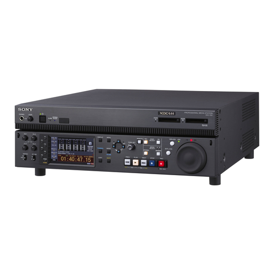
PROFESSIONAL MEDIA STATION
XDS-1000
The supplied CD-ROM includes operation manuals for the XDS-1000 Professional Media
Station (English, Japanese, French, German, Italian, Spanish and Chinese versions) in
PDF format.
For more details, see "Using the CD-ROM Manual" on page 15.
OPERATION MANUAL
1st Edition (Revised 6)
[English]
Advertisement
Table of Contents

Related Manuals for Sony XDS-1000


Summary of Contents for Sony XDS-1000
- Page 1 PROFESSIONAL MEDIA STATION XDS-1000 The supplied CD-ROM includes operation manuals for the XDS-1000 Professional Media Station (English, Japanese, French, German, Italian, Spanish and Chinese versions) in PDF format. For more details, see “Using the CD-ROM Manual” on page 15. OPERATION MANUAL...
- Page 2 Before operating the unit, please read this manual thoroughly 2. Providing protective earth and retain it for future reference. When this product is installed in a rack and is supplied power from an outlet on the rack, please confirm that the outlet is provided with a suitable protective earth WARNING connection.
- Page 3 Union legislation shall be addressed to the authorized representative, Sony Deutschland GmbH, Hedelfinger Ce produit a été fabriqué par ou pour le compte de Sony Strasse 61, 70327 Stuttgart, Germany. For any service or Corporation, 1-7-1 Konan Minato-ku Tokyo, 108-0075 Japon.
- Page 4 (Wohnbereich), E2 (kommerzieller und in beschränktem Maße industrieller Bereich), E3 (Stadtbereich im Freien) und E4 (kontrollierter EMV-Bereich, z. B. Fernsehstudio). Dieses Produkt wurde von oder für Sony Corporation, 1-7-1 Konan Minato-ku Tokio, 108-0075 Japan hergestellt. Bei Fragen zur Produktkonformität auf Grundlage der Gesetzgebung der Europäischen Union kontaktieren Sie bitte...
-
Page 5: Table Of Contents
Supplying Power ................31 Initial Setup ..................31 Front Panel Tilt Mechanism............33 Connections and Settings ............34 Connections for using Content Browser and non-Sony nonlinear editors ..................34 Connections for cut editing..............34 Synchronization Reference Signals ..........39 Setting System Frequency ............40 Setting Time Data ................ - Page 6 Function menu settings................ 44 Handling Memory Cards ............... 47 About memory cards ................47 Inserting/removing an SxS memory card ..........49 Switching between SxS memory cards ..........49 Chapter 4 Recording, Playback and Copying Recording ..................50 Preparations for recording ..............50 Carrying out recording ................
- Page 7 Playing a clip using thumbnail search ..........72 Setting clip flags .................. 73 Locking (write-protecting) clips ............73 Deleting clips ..................73 Copying clips ..................74 Setting the index picture frame............74 EDL Editing ..................75 What is EDL editing? ................75 Creating and editing EDLs ..............
- Page 8 Appendix Important Notes on Operation............ 120 About the LCD panel ................ 120 Precautions for products with built-in HDD ........120 Periodic Maintenance..............122 Operating hours meter ............... 122 Troubleshooting ................123 Alarms ....................123 Error messages .................. 129 Specifications ................129 About DVB-ASI Input/Output (When the Optional PDBK-202 Is Used) ..................
-
Page 9: Features
This unit is equipped with hard disk drives (HDDs) for internal storage. These HDDs provide 1 terabyte (TB) of The XDS-1000 is a full-HD (1920 × 1080 and 1280 × 720) data storage, allowing you to record up to about 30 hours hybrid media deck equipped with hard disk drives in the HD422 50 Mbps recording format. - Page 10 HD downconvert function The unit is provided with a downconvert function. HD clip 1) MPEG HD is a registered trademark of Sony Corporation. playback signals can be downconverted to SD signals and 2) SDI recording only supported for 35 Mbps, and playback only supported then output as SD-SDI or composite signals.
- Page 11 • System timecode input • Remote control - RS-422A (D-sub 9-pin) (2) (In addition to the Sony 9-pin VTR protocol, this unit supports the Video Disk Control Protocol (VDCP).) - Video remote (D-sub 9-pin) (1) - GPIO (D-sub 15-pin) (1)
-
Page 12: System Configurations
System Configurations The figure below shows devices and media that can be • Satellite news gathering (SNG) system (see page 13) used with this unit. • Ingesting/editing system (see page 13) You can use this unit and these devices to configure the •... -
Page 13: Satellite News Gathering (Sng) System
Satellite news gathering (SNG) system The following figure shows an example of SNG system in which this unit is used as both server and backup recorder. On the satellite truck DVB-ASI TS signal This unit This unit DVB-ASI SDI signal TS signal Playout Camcorder... -
Page 14: Live Production System
Live production system The following figure shows an example of sports relay or live recording system in which this unit is used as both editing feeder and backup recorder. Slow-motion/replay controller RS422 (VDCP) This unit Slow-motion/ replay video Live video (SID signal) SDI signal Camcorder Monitor... -
Page 15: Using The Cd-Rom Manual
Adobe Reader. In such a case, install the latest version you can download from the URL mentioned in “Preparations” above. Note If you have lost or damaged the CD-ROM, you can purchase a new one to replace it. Contact your Sony service representative. Using the CD-ROM Manual... -
Page 16: Front Panel
Names and Functions of Parts Chapter Front Panel The names and symbols of buttons and knobs on the front Orange: Function when the button is operated with the panel are color coded according to function. SHIFT button held down. White: Function when the button or knob is operated Blue: Function related to thumbnail operations. - Page 17 c On/standby (1) button and indicator h KEY INHI (inhibit) switch When the main power switch on the rear panel is in the on This turns key operation inhibit mode on or off. position, this switches the unit between the operating state (the indicator is lit green) and the standby state (the 1 Port and media selection section indicator is lit red).
- Page 18 c INTERNAL (internal storage) button a CH-1/ALL CH, CH-2 to CH-4 (audio level) This button selects internal storage (hard disk drives) as adjustment knobs the operation target media. Depending on the setting of the VARIABLE switch, these adjust the input audio or playback audio levels of channels d MEMORY button 1 to 4.
-
Page 19: Display Button
4 Display/menu control section 5 MENU button 4 THUMBNAIL button 3 DISPLAY button 1 Function buttons (F1 to F6) 2 Display 6 PAGE/HOME button 7 COPY button 8 RESET/RETURN button 9 SHIFT button q; Arrow buttons and IN/OUT indicators qa PUSH SET knob a Function buttons (F1 to F6) switched to a clip list screen.) When pressed again, returns These buttons are enabled when the function menu (see... - Page 20 c NEXT button RETURN button: In clip list screens, returns to the previous procedure. Press this button, turning it on, to jump to the next clip and show the first frame. During chase play, play jumps to the i SHIFT button last frame that is playable at that time.
-
Page 21: Display Screen
6 Shuttle/jog/variable-speed playback x (red): Lights during still image display. control section e Shuttle/jog dial The dial switches between shuttle/variable-speed mode and jog mode each time that you press it all the way in. 1 SHTL/JOG button Shuttle/variable-speed mode: The dial is in the raised 2 VAR/JOG button position. - Page 22 1 Function menu 2 Audio input display/audio level meters 3 System information 4 Media status display 5 Recording/playback format 6 Clip information 7 Operation status display 8 Time data display area 9 Status display area a Function menu Display Input signal Use the PAGE/HOME button to display this menu, and to switch between the pages (HOME, P1 to P5) of the menu.
- Page 23 c System information e Recording/playback format In 1-in/1-out mode, this displays the recording format when a record port is selected or the playback clip format when a playback port is selected. In VTR mode, this A Reference signal displays the format of the clip being played. B Video input display Codec A Reference signal: This displays the type of reference...
- Page 24 g Operation status display Display Type of time data Displays icons indicating the operation status of this unit. User bits generator value Icon Description F Time data: Normally displays timecode or VITC, 1080/720 cross-convert output according to the selection made with TCR on page P4 TC of the function menu.
- Page 25 E Network disconnection indicator: Lights when remote connection to SxS memory card from an external device is not permitted. Permitting remote connection or disconnecting remote connection is set in the function menu. For details, see “Disconnecting remote connection to media” (page 80). F Network connection display: Lights while data is being exchanged with a network connected external device.
-
Page 26: Rear Panel
Rear Panel 2 DVB-ASI OUTPUT connector 3 HDMI OUTPUT connector 4 REF. VIDEO INPUT connectors 2 Timecode input/output section (see page 29) 1 PCIe expansion slot 5 Redundant power supply unit installation section 1 HD/SD-SDI signal input/output 3 Power supply section section (see page 27) (see page 29) qd COMPOSITE OUTPUT 1, MONI/2 connectors... - Page 27 HOME page of the function menu is set to “ON”. port. Connect a controller that supports the VDCP 1) You can set E-E signal output at all times using setup menu item 156 protocol or the RS-422A Sony 9-pin VTR control MONITOR OUT SELECT to REC port. protocol.
- Page 28 a HD/SD-SDI INPUT (HD-SDI/SD-SDI signal input) CHAR SEL on the HOME page of the function menu and connector (BNC type) with the setting for setup menu item 027 SD This inputs an HD-SDI or SD-SDI format video/audio CHARACTER. You can always disable to superimpose signal.
- Page 29 the data independent of the setting for CHAR SEL with the Note setting for setup menu item 027. Before turning the main power off, always check to be sure 1) You can set E-E signal output at all times using setup menu item 156 that the on/standby indicator on the front panel is lit in red MONITOR OUT SELECT to REC port.
- Page 30 5 Analog audio signal input/output 1) You can set E-E signal output at all times using setup menu item 156 MONITOR OUT SELECT to REC port. section See “Basic Operations of the Function Menu” (page 44) for more information about the MONITR L and MONITR 1 ANALOG AUDIO INPUT 1, 2 connectors R settings.
-
Page 31: Supplying Power
Preparations Chapter Supplying Power Initial Setup Connect the AC power input connector to an AC power This unit is shipped with the area of use, system frequency, source using the specified AC power cord. To supply and current date and time still unset. power, set the main power switch on the rear panel to on, Therefore, you need to make initial setup settings before and then press the on/standby (1) button on the front panel... - Page 32 Note The time zone is reset to the factory default when you execute the maintenance menu item M49: RESET ALL SETUP. You will need to set it again. The date and time are not reset. Turn the PUSH SET knob to select the area of use. Display UC (for regions outside Japan) or J (for Japan), and then press the SET function button (F5).
-
Page 33: Front Panel Tilt Mechanism
Note Front Panel Tilt The angle cannot be fixed if you pull the front panel past Mechanism position 3 all the way out to the return position. To fix the front panel, return it to position 0 and then pull it out to the desired angle. -
Page 34: Connections And Settings
You can also access to this unit from a nonlinear editor that The following figure shows a cut editing system is not a Sony product via FTP/CIFS, and use this unit as a comprising this unit as a player. material server. - Page 35 When using an editing control unit BVE-700/700A The following figure shows a cut editing system comprising this unit as a player, an HDW-M2000/M2000P unit as a recorder, and a BVE-700/700A as an editing control unit. This unit can also be used as a recorder. To HD-SDI input connector Reference video signal HD video monitor...
- Page 36 Setting of VTR constants When connecting an editing control unit (BVE-700/700A/ 2000) to use with this unit, set VTR constants as follows. System frequency VTR constant 59.94i/59.94P/29.97P 50i/50P/25P 23.98P Using the RM-280 Editing Controller The following figure shows a cut editing system The RM-280 can perform tasks, such as thumbnail comprising this unit as a player, an HDW-M2000/M2000P searches, because the required VTR constants have been...
- Page 37 Settings on each unit Device Settings HDW-M2000/M2000P (recorder) • REMOTE 1 (9P) button: Lit • REF.VIDEO INPUT connector 75 Ω termination switch: OFF • Audio selection function switching button INPUT button: HDSDI • Function menu HOME >F1 (VID. IN): SDI •...
- Page 38 Using the editing functions of the recorder (controlling through REMOTE (9P) connector) The following figure shows a cut editing system comprising this unit as a player, and an HDW-M2000/ M2000P unit as a recorder. In this example, video and audio signals are connected by HD-SDI, and control signals are transferred via a REMOTE (9P) connector.
-
Page 39: Synchronization Reference Signals
Synchronization Reference Signals The synchronization reference signal generator of this unit setting of OUT REF on the HOME page of the function synchronizes to a reference signal input to the REF. menu, and on the type of the selected input signal. Video VIDEO INPUT connector or to a video input signal. -
Page 40: Setting System Frequency
Setting System Setting Time Data Frequency Setting timecode This unit can record and play back video at the system There are the following four ways of recording timecode: frequencies of 1080/59.94i, 50i, 29.97P, 25P, and 23.98P Internal Preset mode: This records the output of the or 720/59.94P and 50P. - Page 41 Setting an initial timecode value To record timecode synchronized to the station’s reference time Press the CNTR SEL function button on the HOME On page P4 TC of the function menu, set TCG to “SYS”. page of the function menu, and select TC. This selects recording of timecode synchronized to a broadcast station reference timecode signal input to the Press the TCG SET function button (F3).
-
Page 42: Setting User Bits
To check the synchronization to the external Superimposed Text signal Press the REC/PB2 PORT button to select the recording Information port. Check that the timecode value shown in the time data display coincides with the external timecode value. The video signal output from the following connectors on this unit contains superimposed text information, To record external timecode directly including timecode and alarm messages. - Page 43 Display Meaning Display Operation mode TC reader timecode Block A Block B TC reader user bits data F.FWD Fast forward search TCR. VITC reader timecode F.REV Fast reverse search UBR. VITC reader user bits data PLAY Playback mode (servo unlocked) TC generator timecode PLAY LOCK...
-
Page 44: Basic Operations Of The Function Menu
To change the setting of a function menu Basic Operations of the item Use the function buttons. Function Menu To select the value of the setting item Press the function button to the left of each setting item to The function menu provides access to frequently used change the value of the item. - Page 45 Item Setting Item Setting F5: MONITR R Selects the channel to monitor as the F5: A3 INPUT Selects the audio input signal to assign right monitor channel. to audio channel 3. CH1, CH2, CH3, CH4, CH5, CH6, CH7, SDI: Audio signal embedded into SDI signal CH1/2, CH3/4, CH5/6, CH7/8 (MIX) ANALOG1: Input signal to the ANALOG...
- Page 46 P4 TC page Item Setting F4: A8 INPUT Selects the audio input signal to assign Item Setting to audio channel 8. F1: TCG Selects the timecode signal to which the SDI: Audio signal embedded into SDI internal timecode generator signal synchronizes.
-
Page 47: Handling Memory Cards
Item Setting unit F1: INDEX Sets the index picture (thumbnail) of a Use the following Sony memory cards with this unit. clip being played back (see page 74). F2: ERR LOG Displays the error log screen. SxS PRO+ • SBP-64B (64 GB) F3: CREATE Creates a new EDL (see page 76). - Page 48 Memory card operations supported by this • Guard against accidents and inadvertent data loss by unit backing up the data stored on SxS memory cards. Sony cannot be responsible for any consequences of damage UDF-format memory cards (SxS PRO+, SxS PRO, to or loss of data stored on SxS memory cards.
-
Page 49: Inserting/Removing An Sxs Memory Card
Inserting/removing an SxS memory card Memory card slots MEMORY ACCESS A/B lamps Press the button once to release the lock Press the eject button again to remove the card. MEMORY button Eject buttons To insert an SxS memory card Insert the SxS memory card into the card slot. Note Data are not guaranteed if the power is turned off or a Insert with... -
Page 50: Chapter 4 Recording, Playback And Copying
Recording, Playback and Copying Chapter Simultaneous recording Recording Records simultaneously to internal storage and SxS memory card. Note This section describes video and audio recording on the unit. Simultaneous recording is disabled when maintenance menu item M397 PORT CONFIGURATION is set to See page 44 “Basic Operations of the Function Menu”... - Page 51 Recording starts. the internal storage continues. If you insert a recordable SxS memory card when a message is displayed to To stop recording, press the STOP button. confirm whether you wish to replace the card and continue the recording or to stop the recording, This unit enters a stop mode.
-
Page 52: Mixed Recording Of Clips In Different Formats On The Same Media
A shot mark 1 or 2 is set as an essence mark, respectively Linear Editing on the frame being recorded. You can set shot marks for clips being recorded in internal storage when recording simultaneously to SxS memory card. Note The shot marks can also be set during playback. -
Page 53: Connections
Item Setting Note Audio/Non-audio To perform insert editing of non-audio Editing of the MPEG HD420 format is not supported. (data) (data), set maintenance menu item M37: AUDIO CONFIG >M372: NON- AUDIO INPUT to “data”. Editable video and audio signals Notes This unit supports editing of the following signals on video •... -
Page 54: Editing Operations
For preread editing, set “PREREAD” on page P5 OTHER Editing operations of the function menu to ON (see page 47). Notes • When the IN and OUT points are not set in the same clip, Audio source insert editing is performed only for the clip containing the IN point. -
Page 55: Playback
Make the necessary connections for preread editing. Playback After selecting the desired insert editing mode, carry out preread editing. This section describes playback of video and audio on the When preread editing is completed, disconnect the unit. connections. Before starting playback, make the following settings and Set PREREAD on page P5 OTHER of the function adjustments. - Page 56 Playback in clip mode Note The available playback types include normal playback, When playback is stopped on an EDL, the playback high-speed playback in the forward or reverse directions, position is not saved. and jog, shuttle, and variable-speed playback. Playback stops when it reaches the start or end of the clip/EDL.
-
Page 57: Selecting A Clip Or An Edl
Playback operation Notes • Clips and EDLs on SxS memory cards cannot be played This section describes the following types of playback: in this mode. Normal playback: Playback at normal speed • Repeat playback is disabled when menu item 158 Playback in jog mode: Variable-speed playback, with the PLAYBACK MODE FOR INTERNAL is set to speed determined by the speed of turning the jog dial... - Page 58 Press the SHTL/JOG button, turning it on. JOG indicator: Lit Turn the shuttle/jog dial to the desired angle corresponding to the desired playback speed. Playback in shuttle mode starts. To stop playback in shuttle mode, return the shuttle/ jog dial to the center position, or press the STOP button.
-
Page 59: Playback Operations Using Thumbnails
Playback in variable-speed mode starts. To jump to the last frame that is playable at that time To stop playback in variable-speed mode, return the Press the NEXT button. shuttle/jog dial to the center position, or press the STOP button. Note To alternate between normal-speed playback and For MPEG recording, the minimum time difference... -
Page 60: Copying
• Normal copy Copying You can select one or more clips and copy/duplicate on copy source media or copy all clips on an SxS memory card at one time. • Partial copy Overview You can select one clip on copy source media and copy a specified part of the clip (see page 62). - Page 61 Limitations Do one of the following to select the clip to copy. • When you copy a clip with a duration that exceeds six • Turn the PUSH SET knob. hours, the clip is divided into separate clips at each six- •...
- Page 62 To copy clips from an SxS memory card to When two SxS memory cards are inserted Press the MEMORY button, and select the copy another SxS memory card source card (A/B). Insert the copy source and copy destination SxS memory cards, then carry out the procedure in “Copying clips to the internal storage”...
-
Page 63: Chase Copy
• Delete the clip in which IN/OUT points are set. • Format the media. Chase copy When a clip is being recorded to the internal storage, that clip can also be duplicated/copied on the internal storage, to an SxS memory card at the same time. IN indicator If FTP connections are made between this unit and a OUT indicator... -
Page 64: Transcode Copy
Press the ABORT function button (F1), and then press Handling of the Internal the YES (F5) button. The data having already been copied remains. Storage When Recording To stop the recording, press the STOP button. Does Not End Normally When the copy processing is completed successfully, (Salvage Function) the message “Copy was Completed.”... -
Page 65: Chapter 5 Operations In Clip List Screens
Operations in Clip List Screens Chapter Overview Use clip list screens to search for scenes, play scenes found You can switch between the details view and the by searching, select clips to copy, and perform other thumbnails view of clip list screens. operations related to clips. -
Page 66: Information And Controls In Clip List Screens
d Clip number/total number of clips Information and controls in clip list Displays the total number of clips (including EDLs) on the screens selected media, and the number of the selected clip (or EDL). Note e Scrollbar When not all of the thumbnails can be displayed in the 59.94P/50P clips in 4K or HD material are not displayed in thumbnail display area, the position of the slider shows the the clip list display screens. - Page 67 l EDL mark Details view The mark appears when the item is an edit decision list (EDL). m Recording or playback status icon When the recording media is the internal storage, an icon appears to indicate the recording or playback status ( : recording, : playing, : chase play).
- Page 68 Thumbnail display items A copy playback icon ( ) appears to indicate that the clip cannot be played back directly, but copy playback is possible. During recording and playback, an icon appears to indicate the recording or playback status ( : recording, playing, : chase play).
-
Page 69: Clip Menu
d Clip number/total number of clips a Selection frame Displays the total number of clips on the selected media Indicates that the thumbnail is selected. To select another and the number of the clip whose expanded thumbnails are thumbnail, move the frame (see page 71). Multiple currently displayed. -
Page 70: Clip F Menu
Item Sub-item Function Clip F Menu Lock Unlock Clips Lock Selected Locks the selected (SHIFT + STOP) Clips clips. The clip list screens provide the Clip F Menu, which can be accessed directly with function buttons. Lock All Clips Locks all clips on the selected media. -
Page 71: Clip Operations
operation, disconnect the remote connection using the Clip Operations NET ENA command. Item Function F6: NET ENA Permits or disconnects remote connection from an external device to Note SxS memory cards inserted in the unit. It The following operations are not available for clips also indicates the current connection availability. -
Page 72: Playing A Clip Using Thumbnail Search
efficient way to review the selected clip and search for See page 69 for more information about chapter target scenes. You can specify 12, 144, or 1728 divisions. thumbnail screen. In the clip thumbnail screen, select the thumbnail of a clip or the icon of an EDL with chapters set. -
Page 73: Setting Clip Flags
To play the clip To lock clips Select the clip you have found, and then press the PLAY In a clip list screen, select the clips that you want to button. lock (multiple selections possible). This step is not needed if you lock all clips. Setting clip flags Display the Clip Menu. -
Page 74: Copying Clips
Place the unit in standby off mode to delete clips in VTR Press the STOP button at the frame you want to be the mode. To switch to standby-off mode, press and hold the index picture frame, to obtain a still frame display. SHIFT button and then press the STOP button. -
Page 75: Edl Editing
EDL Editing Clips on media Clip 1 Clip 3 Clip 4 Clip 2 (C0002) (C0001) (C0003) (C0004) What is EDL editing? EDL (E0001) EDL editing is a function which allows you to select material (clips) from the material recorded on media and Sub clip 1 Sub clip 2 Sub clip 3... - Page 76 Create EDLs: Use the CREATE NEW EDL command to create an EDL containing the selected clips. Add sub clips: Use the ADD TO CURT.EDL command to add the clips you want to use to an EDL. You can add up to 300 sub clips to one EDL. Delete sub clips: Use the REMOVE command to delete specified sub clips from an EDL.
- Page 77 Display the P1 EDL page of the Clip F menu and press the SET CURT.EDL (F1) button. The selected EDL becomes the current EDL. When the current EDL is specified, the current EDL icon appears in the status display area. Adding in clip list screens See page 65 for information about screen operations.
-
Page 78: Media Operations
To play an EDL Media Operations Note When the internal storage playback mode is set to clip Checking the media information mode, only the selected sub clip can be played. In the chapter thumbnail screen, select the thumbnail In a clip list screen, press the MENU button to display for the sub clip you want to start playing. -
Page 79: Sxs Memory Card Operations
To display hidden text confirmation dialog appears asking if you want to For items displaying b or B, press the < or , button to execute formatting, execute step 6 once more. scroll the text by one character at a time. Pressing the M or m button displays the first character or When formatting is completed, select “Exit”, and then last character, respectively. -
Page 80: Disconnecting Remote Connection To Media
Disconnecting remote connection to media You can perform operations on an SxS memory card inserted in the unit using a remote connection from an external device. While using a remote connection, clip- related display and operation is disabled on the unit. When you wish to perform media operations from the unit, use the following procedure to disconnect the remote connection and disable connection from external devices. -
Page 81: Overview
File Operations Chapter Overview A remote computer can be connected to this unit and used to operate on recorded data which has been saved in data files, such as video and audio data files. To perform file operations, use either of the following methods to interconnect this unit and a computer. -
Page 82: File Operation Restrictions
File operation restrictions This section explains which operations are possible on Note files stored in each directory. File names are not case-sensitive. “Read” and “write” are defined as follows. Read: Read data sequentially from the start to the end of the file. - Page 83 File name Content Operations Read Write Rename Create Delete M01.XML Metadata file generated automatically when E01.SMI file is created. Other files Files other than the above – – – a) The unit can handle files with user-defined names in the “*” part. e) When an *E01.SMI file is deleted, an *M01.XML file with the same name b) Only files which can be written by XDS devices in the “*”...
-
Page 84: Ftp File Operations
For details, see “To check the assigned IP address” (page 118). The password is set to the model name (“xds-1000”) when the unit is shipped from the factory. 1) This unit is able to acquire an IP address automatically from a DHCP server. - Page 85 Send this command to complete the login process. Command syntax: STRU <SP> <structure-code> Command syntax: PASS <SP> <password> <CRLF> <CRLF> Input example: PASS xds-1000 <structure-code> can be any of the following. However, QUIT for XDS devices, the structure is always “F”, regardless of Terminates the FTP connection.
- Page 86 The following data is transferred, depending on whether Notes <path-name> specifies a directory or file. • For *.MXF files or *E01.SMI files, the UMID of the • Directory specified: A list of the files in the specified copy source file is not saved. However, it is saved if an directory •...
- Page 87 - CODEC type Moves to a directory as follows, depending on whether a - Frame rate directory is specified with <path-name>. - Number of audio channels • Directory specified: To the specified directory - Duration • No specification: To the root directory - UMID Input example: CWD Clip •...
- Page 88 Notes Notes • You cannot specify such section that exceeds the file • This command remains in effect until a STOR command size. is executed, or (if no STOR command is executed) until • If the file name character string contains one or more the FTP connection is terminated.
-
Page 89: Recording Continuous Timecode With Ftp Connection
The Connect As... dialog appears. Enter the user name “admin” and the password, and click OK. The password is set to the model name (“xds-1000”) when the unit is shipped from the factory. Click Finish. The network drive allocation is complete when the password is verified. -
Page 90: Menu System Configuration
Menus Chapter Menu System Setup Menu Configuration The setup menu system of this unit comprises the basic setup menu and extended setup menu. The settings for this unit use the following menus. Basic menu Setup menu This menu is used to make settings relating, for example, The setup menu system of this unit comprises the basic to the following. -
Page 91: Items In The Basic Menu
Item group Function Refer to Item group Function Refer to Items Settings relating to control page 97 Items Settings relating to the page 102 100 to 199 panels 650 to 699 metadata and UMID Items Settings relating to the remote page 99 Items Settings relating to video... - Page 92 Item number Item name Settings DISPLAY INFORMATION Determine the kind of text information to be output from the HD-SDI SELECT OUTPUT1 2 (SUPER), SD-SDI OUTPUT1 2 (SUPER), HD-SDI MONITOR/ OUTPUT2 2 (SUPER), SD-SDI MONITOR/OUTPUT2 2 (SUPER), or COMPOSITE OUTPUT MONI/2 connector. time data &...
- Page 93 Item number Item name Settings SYSTEM FREQUENCY Specify whether to enable switching the system frequencies. SELECT MENU off: Do not enable switching the system frequencies. on: Enable switching the system frequencies. You can switch between the following frequencies. 1080/59.94i, 50i, 29.97P, 25P, 23.98P, 720/59.94P, 50P For details about switching the system frequencies, see page 40.
-
Page 94: Basic Menu Operations
Item number Item name Settings STORED OWNERSHIP Specify whether to enable changing UMID ownership information settings (COUNTRY, ORGANIZATION and USER). off: Do not enable. on: Enable. See “Using UMID Data” (page 134) for more information about UMID. RECORDING FORMAT Set the recording format. HD422: HD422 HD420 HQ [420HQ]: HD420 HQ HD420 HQ1920 [HQ192]: HD420 HQ1920... - Page 95 To display a setup menu, press the MENU button. Current setting The currently selected menu item is displayed in reverse video. Currently selected item Group name for the currently selected item Press the PUSH SET knob or the SELECT function button (F2).
-
Page 96: Menu Bank Operations (Menu Items B01 To B13)
To return all settings to their factory default sure to press the SAVE function button (F5) after making the settings. settings Press the MENU button to display the setup menu. To return menu settings to their factory default settings Press the RESET button. After changing menu settings, use the following procedure The message “INITIALIZE ALL ITEMS TO to return the settings to their factory default settings... -
Page 97: Items In The Extended Menu
To save the current settings in a menu bank To recall settings saved in a menu bank Select a menu item from B11 “SAVE SETUP BANK- Select a menu item from B01 “RECALL SETUP 1” to B13 “SAVE SETUP BANK-3” using the PUSH BANK-1”... - Page 98 FTP/CIFS and handled on the network. Note When using a nonlinear editor that is not a Sony product, please contact the maker to confirm whether it is possible or not to receive clips output by the chase output function using MXF V1.3 format.
- Page 99 Select the protocol used with a REMOTE (9P) connector, for each port. Sub-item #2 (PB) Select the protocol used with the playback port. VTR: Sony 9-pin VTR protocol VDCP: VDCP protocol Note When maintenance menu item M397 PORT CONFIGURATION is set to “VTR mode”, the protocol is set to “VTR”...
- Page 100 Menu items in the 300s, relating to editing operations Item number Item name Settings ANALOG AUDIO EDIT PRESET Select methods for setting the edit presets of the digital audio channels REPLACE FOR CH1 CH1 to CH4 of this unit. Make these settings when using an editor (PVE- 500, BVE-600, etc.) or remote control unit without a function to control ANALOG AUDIO EDIT PRESET digital audio edit presets.
- Page 101 Menu items in the 600s, relating to the timecode, metadata, and UMID Item number Item name Settings VITC POSITION In 59.94i/59.94P/ Select the line into which to insert VITC signals (SD output) SEL-1 29.97P mode 12H to 16H to 20H: Any line from line 12 through line 20. Notes •...
- Page 102 Menu items in the 600s, relating to the timecode, metadata, and UMID Item number Item name Settings UPCONV EMBEDDED VITC Select the source of the VITC embedded into output HD-SDI signal when up converting during playback of an SD clip. VITC: Select the VITC of the SD clip.
- Page 103 Menu items in the 600s, relating to the timecode, metadata, and UMID Item number Item name Settings METADATA ITEM OUT Specify whether to include the information from recorded VANC packets in data items in the DATA ITEM section of MXF files. off: Do not include VANC packet information in DATA ITEM.
- Page 104 Menu items in the 700s, relating to video control Item number Item name Settings INTERNAL VIDEO SIGNAL Select the test signal to be output from the internal test signal generator. GENERATOR When INT SG on page P1 INPUT of the function menu is set to “ON”, the internal test signal generator operates to output the selected test signal.
- Page 105 Menu items in the 700s, relating to video control Item number Item name Settings INPUT VIDEO BLANKING Switch blanking on or off for lines in the vertical blanking interval of input video signals. Lines can be specified individually. Y/C signals and odd/ Sub-item even fields are blanked simultaneously.
- Page 106 Menu items in the 700s, relating to video control Item number Item name Settings PR LEVEL (HD) Adjust the PR level of the high-definition video signal output from the HD-SDI OUTPUT or HDMI OUTPUT connectors. –2048 to 0 to 846 SETUP LEVEL (HD) Adjust the setup level of the high-definition video signal output from the HD-SDI OUTPUT or HDMI OUTPUT connectors.
- Page 107 Menu items in the 800s, relating to audio control Item number Item name Settings SDI AUDIO OUTPUT SELECT Select the audio signals to assign to SDI audio output channels. Sub-item CH1/CH2 tr1/2: Tracks 1 and 2 assigned to audio output channels 1 and 2. tr3/4: Tracks 3 and 4 assigned to audio output channels 1 and 2.
- Page 108 Menu items in the 900s, relating to digital process Item number Item name Settings Sets the parameters for DVB-ASI output, and specifies the number of the a) b) DVB-ASI SETTING program to receive when DVB-ASI signals are input. Sub-item I/O MODE Sets DVB-ASI input /output.
- Page 109 Menu items in the 900s, relating to digital process Item number Item name Settings PID(VIDEO) Changes the VIDEO packet PID value for DVB-ASI output. 30 to 810 to 1FFE: Set PID value (as a hexadecimal value). You can set the value over the range from 30 to 1FFE in 1 units (or 20 units, when the SHIFT button is held down).
- Page 110 Menu items in the 900s, relating to digital process Item number Item name Settings LEVEL DEPEND THRESHOLD Adjust the down-converter image enhancer. Set the luminance range for (DC) edge enhancement. 0 to 8 to FH H DETAIL FREQUENCY (DC) Adjust the down-converter image enhancer. Set the central frequency for edge enhancement.
-
Page 111: Extended Menu Operations
Menu items in the 900s, relating to digital process Item number Item name Settings IMAGE ENHANCER (INPUT UP Set up the operation of the up converter image enhancer for SD input, separately from the settings for playback (menu items 950 to 959). CONVERTER) Sub-item pb: While SD signals are input, make the behavior of the image... - Page 112 The maintenance menu appears on the video monitor screen. Turn the PUSH SET knob to select “M4 SETUP MAINTENANCE”, then press the PUSH SET knob or the SELECT function button (F2). The sub-items of M4: SETUP MAINTENANCE appears. Turn the PUSH SET knob to select “M40 EXTENDED MENU”, then press the PUSH SET knob or the SELECT function button (F2).
-
Page 113: Maintenance Menu
Maintenance Menu Items in the maintenance menu The following tables show the items in the maintenance • The underlined values are the factory defaults. menu. • The values in the “Setting” column are the values that Refer to the Maintenance Manual for information about appear in settings screens. - Page 114 M3: OTHERS: Other setting items Item Setting M37: AUDIO M370: HEAD ROOM Select the audio reference level (headroom). CONFIG –20dB, –18dB, –16dB, –12dB, EBUL Note EBUL can be selected only when the system frequency is 50i/25P. M371: DATA LEN Select the audio channel configuration for IMX recording. 16bit x 8ch [16x8]: 16-bit, 8-channel configuration 24bit x 4ch [24x4]: 24-bit, 4-channel configuration M372: NON-AUDIO...
- Page 115 M3: OTHERS: Other setting items Item Setting IN 1 Set the command to be assigned to pin IN 1. PB-STOP COMMAND [P.STP] IN 2 Set the command to be assigned to pin IN 2. PB-PLAY COMMAND [PLAY] IN 3 Set the command to be assigned to pin IN 3. PB-RECUE COMMAND [RECUE] IN 4 Set the command to be assigned to pin IN 4.
- Page 116 M4: SETUP MAINTENANCE: Items relating to the setup menu Item Setting M40: EXTENDED MENU Select whether to display the extended menu. DISABLE [dis]: Do not display. ENABLE [ena]: Display. M48: AUTO RECALL Select whether to recall settings automatically from a menu bank when the system is powered on, and if so which menu bank to recall from.
-
Page 117: Maintenance Menu Operations
M5: NETWORK: Items relating to network settings Item Setting M5F: RESET NET CONFIG Reset network settings to the factory defaults. Push the SAVE function button (F5): Reset. Push the MENU button: Return to the next highest menu level without executing the reset. - Page 118 To cancel changing a setting To change the value of a digit Before pressing the SAVE function button (F5), press the Turn the PUSH SET knob. MENU button. Turning clockwise increases the value, and turning The menu disappears from the video monitor screen, counterclockwise decreases the value.
- Page 119 This returns to the NETWORK menu. In the NETWORK menu, press the SAVE function button (F5). When the message “NETWORK CONFIG WAS CHANGED. PLEASE REPOWER.” appears, power the unit off and then on again with the on/standby button. Maintenance Menu...
-
Page 120: Appendix
In the event of operating problems If you should experience problems with the unit, contact Precautions for products with built- your Sony service or sales representative. in HDD Use and storage locations This unit has a built-in hard disk drive (HDD). The HDD Store in a level, ventilated place. -
Page 121: Power Off
HDD replacement • When transporting the unit, use the specified packing material. When transporting on a dolly or similar, use a Contact your Sony service or sales representative about type which does not transmit excessive vibrations. periodic replacement of the HDD. -
Page 122: Periodic Maintenance
PC monitor connected to the MONITOR connector. Use the information as a guide in scheduling periodic maintenance. For periodic maintenance, contact your Sony service or sales representative. Display modes of the operating hours meter... -
Page 123: Troubleshooting
Example alarm in video monitor screen When an alarm is displayed, remove the alarm cause by following the action to take. If the alarm display does not disappear, contact your Sony service or sales representative. When the unit is powered on... - Page 124 When a memory card is inserted Alarm message in status Alarm message in video monitor screen Description/action display area Unknown Media(A/B) UNKNOWN MEDIA(A/B). The inserted memory card has been partitioned, or it PLEASE CHANGE. contains more clips that the maximum that can be handled by this unit.
- Page 125 Alarm message in status Description/action display area TC EXT! This appears when TCG on page P4 TC of the function menu is set to “EXT”, and you try to preset timecode or user bits by setting PRST/RGN to “PRESET”. Set TCG to “INT” (see page 46). REGEN mode! This appears when PRST/RGN on page P4 TC of the function menu is set to “TC”...
- Page 126 During playback operations Alarm message in status Alarm message in video monitor screen Description/action display area ILL. PLAY! ILLEGAL PLAYBACK. Normal playback is not possible. MEM. Empty! MEMORY EMPTY !! Playback is not possible because a buffer underflow has occurred in the playback buffer memory. Media Data Error! MEDIA DATA ERROR DETECTED.
- Page 127 Alarm message in status Alarm message in video monitor screen Description/action display area FAN(1/2) Error FAN(1/2) ERROR. Contact your Sony service or sales representative. Note FAN(1/2) Warning FAN(1/2) WARNING. The unit will not stop operating, but if you continue to DC Power Warning DC POWER STATUS IS NOT NORMAL.
- Page 128 Alarm message in video monitor screen Description/action display area CF Warning IT IS NECESSARY TO REPLACE CF Contact your Sony service or sales representative. DISK. PLEASE CONTACT SERVICE. Note The unit will operate, but if you continue to use it, the CF disc may be damaged and all information may be lost.
-
Page 129: Error Messages
Error messages Specifications Error codes appear in the status display area when an error (usually a hardware problem) occurs. In addition, both General error messages and error codes appear on the video monitor screen or on a PC monitor connected to the External dimensions (w/h/d, excluding projections) MONITOR connector. - Page 130 System Composite outputs Frequency response Recording/playback format (baseband 0.5 to 5.75 MHz, +0.5/–2.0 dB recording) S/N (Y) 53 dB or more Video/audio MPEG-2 422P@HL, 50 Mbps, 8 ch/24 Y/C delay ±20 ns or less bit/48 kHz K-factor (K2T) 1.0% or less MPEG-2 MP@HL, 35 Mbps/VBR, 4 ch/ 16 bit/48 kHz Processor adjustment range...
- Page 131 Timecode inputs Remote control connectors TIME CODE IN REMOTE (9P) D-sub 9-pin (2) female, complying with BNC type (1), SMPTE timecode, 0.5 to RS-422A 18 Vp-p, 3.3 kΩ, unbalanced VIDEO CONTROL SYSTEM TC INPUT D-sub 9-pin (1), female, complying with BNC type (1), SMPTE timecode, 0.5 to EIA RS-423 18 Vp-p, 3.3 kΩ, unbalanced...
-
Page 132: About Dvb-Asi Input/Output (When The Optional Pdbk-202 Is Used)
• Always verify that the unit is operating properly as to match that of a device from which DVB-ASI TS before use. SONY WILL NOT BE LIABLE FOR signals are input to this unit or a device to which DVB- DAMAGES OF ANY KIND INCLUDING, BUT ASI TS signals are output from this unit. -
Page 133: Menu Settings
15.00 Mbps to 43.25 Mbps (in steps of 0.01 Mbps) The clip name when recording DVB-ASI TS signals When DVB-ASI TS signals are fed from an XDS-1000/ PD1000/PD2000 unit or a PDW-HR1 which is equipped with the PDBK-202 and recorded on this unit, clips to be recorded can be given the same name as that of clips being fed. -
Page 134: Using Umid Data
Using UMID Data What is a UMID? Metadata is additional information recorded on media along with audio-visual data. It is used to bring greater A UMID (Unique Material Identifier) is a unique identifier efficiency to the flow of operations from material for audio-visual material defined by the acquisition through editing, and to make it easier to find SMPTE-330M-2004 standard. - Page 135 • Recording with UTC time. UTC (coordinated universal Use the PUSH SET knob, – or + function button (F3 or time) is used when recording the UMID. Use of a F4) to select characters to input at the selected universal time system enables uniform management of location.
-
Page 136: Ancillary Data
When the user code is less than 4 bytes, enter the user code Ancillary Data at the beginning of the 4 bytes and fill the remainder of the string with the space character (20h). This user code is determined by the organization. The methods used depend on the organization. -
Page 137: Ancillary Data In Mxf Files
- LINE (line for the VANC to be received): 9LINE (conforming to the SMPTE436M-2006) and can be output. (example) This data can also be input and recorded. - DID (data identification word): 61h - SDID (secondary data identification word): 01h To insert ancillary data into MXF files to •... - Page 138 EIA-708/608 recording and playback HDSDI (VANC) input HDSDI (VANC) output SDSDI (line 21) input SDSDI (line 21) output Composite (line 21) output EIA-608 recording and playback EIA-708/608 EE output In response to closed caption input data that complies with Closed caption data in SDSDI line 21 signals are output to the EIA-708/608 standard, output to EE.
- Page 139 EIA-708 recording and playback EIA-608 t708 HDSDI (VANC) output conversion Down convert SDSDI (line 21) input SDSDI (line 21) output playback Composite (line 21) output EE output after EIA-608t708 conversion In response to closed caption input data that complies with For details, see “To record EIA-608-B standard closed the EIA-608 standard, output that data to EE after caption data in SDSDI line 21 signals after conversion to...
- Page 140 HDSDI (VANC) output 1080 playback Playback of HD clips 1080 clip Down convert playback SDSDI (line 21) output Cross convert and Composite (line 21) output playback 720 clip HDSDI (VANC) output 720 playback Down convert playback SDSDI (line 21) output Composite (line 21) output Playback and down convert playback of HD clips containing EIA-608 data only EIA-608 standard closed caption data recorded in HD clips...
- Page 141 HDSDI (VANC) output 1080 playback Playback of HD clips 1080 clip Down convert playback SDSDI (line 21) output Cross convert and Composite (line 21) output playback 720 clip HDSDI (VANC) output 720 playback Down convert playback SDSDI (line 21) output Composite (line 21) output Ancillary Data...
-
Page 142: Correspondence Between Setting Items Of The Hkdv-900 And Setup Menu Of This Unit
Setting item of Menu item of this unit’s setup menu Correspondence between HKDV-900 DEPEND 938: LEVEL DEPEND THRESHOLD Setting Items of the (DC)/ 957: LEVEL DEPEND THRESHOLD HKDV-900 and Setup (UC) FREQUENCY 939: H DETAIL FREQUENCY (DC)/ Menu of This Unit 958: H DETAIL FREQUENCY (UC) H/V RATIO 940: H/V RATIO (DC)/... -
Page 143: Trademarks And Licenses
AND/OR WAS OBTAINED FROM A VIDEO To meet the requirements of the software copyright PROVIDER LICENSED BY MPEG LA TO PROVIDE holders, Sony is obligated to inform you of the content of MPEG-4 VIDEO. these licenses. For the content of these licenses, see “License1.pdf” in the NO LICENSE IS GRANTED OR SHALL BE IMPLIED “License”... -
Page 144: Glossary
A list of locations in the material a difference of approximately 86 Glossary recorded on a media, arranged in any seconds per day between real time order. and timecode, which causes problems when editing programs in E-E mode units of seconds using the number of AES/EBU Electric-to-Electric mode. - Page 145 section of a UMID contains a globally unique number and a material number for the identification of recorded material. An optional section called the “Source Pack” contains information such as the time and location of recording. A UMID with the Basic section only is called a Basic UMID.
-
Page 146: Index
Clip list screens 65 operations 111 Index chapter thumbnail screen 69 External synchronization 39 details view 67 expand thumbnail screen 68 thumbnails view 66 Features 9 Clip Menu 69 File operations 81 AC power input connector (-) 29 Clip Properties screen 67 Clip directory 82 Accessories Closed caption data 137... - Page 147 JOG indicator 21 On/standby button (1) and indicator Salvage 64 Jog mode 57 SD-SDI MONITOR/OUTPUT2 1, 2 Jog/shuttle direction indicators 21 Operating hours meter 122 connector 28 display modes 122 SD-SDI OUTPUT1 1, 2 (SUPER) displaying 122 connectors 28 exiting 122 Setup menu KEY INHI switch 17 Operation status display 24...
- Page 148 UMID Data 134 USB connector 17, 27 User bits setting 42 VAR/JOG button 21 VARIABLE switch 18 Variable-speed mode 58 VIDEO CONTROL connector 27 Video input display 23 Index...
- Page 149 The material contained in this manual consists of information that is the property of Sony Corporation and is intended solely for use by the purchasers of the equipment described in this manual. Sony Corporation expressly prohibits the duplication of any...
- Page 150 Sony Corporation XDS-1000 Printed in Japan (SYL) 2013.06 32 4-270-117-07 (1) © 2010 Printed on recycled paper.
Need help?
Do you have a question about the XDS-1000 and is the answer not in the manual?
Questions and answers