Table of Contents
Advertisement
Quick Links
Download this manual
See also:
User Manual
Advertisement
Table of Contents

Related Manuals for Avermedia AVerDiGi EB1704HB


Summary of Contents for Avermedia AVerDiGi EB1704HB
- Page 1 ® AVerMedia AVerDiGi EB1704HB WiFi-4 Lite User Manual...
- Page 2 In no event will AVerMedia be liable for direct, indirect, special, incidental, or consequential damages arising out of the use or inability to use this product or documentation, even if advised of the possibility of such damages.
- Page 3 WARNING TO REDUCE RISK OF FIRE OR ELECTRIC SHOCK, DO NOT EXPOSE THIS APPLIANCE TO RAIN OR MOISTURE CAUTION IF THERE IS ANY DAMAGE, SHORTAGE OR INAPPROPRIATE ITEM IN THE PACKAGE, PLEASE CONTACT WITH YOUR LOCAL DEALER. WARRANTY VOID FOR ANY UNAUTHORIZED PRODUCT MODIFICATION NOTICE - INFORMATION IN THIS DOCUMENT IS SUBJECT TO CHANGE WITHOUT NOTICE.
-
Page 4: Table Of Contents
Table of Contents Chapter 1 Introduction................1 Package Content ....................1 1.1.1 DVR unit......................1 1.1.2 WiFi IP Camera ....................1 Features and Specifications.................. 2 Front Panel ......................2 Back Panel ......................4 Setting Up the DVR Unit ..................5 1.5.1 Installing the Hard Disk .................. - Page 5 Recommended system requirements ..............37 Familiarizing with HDD Backup Application ............37 To Backup Recorded Video File................38 Chapter 6 ImageVerification ..............39 To Run the ImageVerification................39 Chapter 7 iEnhance.................. 40 To Use iStable..................... 41 Chapter 8 Using the Remote Programs..........42 Familiarizing the Web Viewer Buttons ..............
-
Page 7: Chapter 1 Introduction
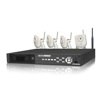
Chapter 1 Introduction Package Content 1.1.1 DVR unit (1) AVerDiGi EB1704HB WiFi unit (2) Remote Control (batteries included) (3) Quick Installation Guide (4) Power Cord * The power cord varies depending on the standard power outlet of the country where it is sold. -
Page 8: Features And Specifications
- Each DVR package contains 4 pieces of IP camera. - If there is any damage, shortage or inappropriate item in the package contents, please contact with local dealer Features and Specifications Support 4 WiFi IP Cameras connection Support 4 Channel Audio Record MPEG-4 compression Multiple clients and dynamic IP supported Motion detection recoding... - Page 9 Name Function Use these buttons in playback mode to switch to display each channel 1/2/3/4/Quad in full screen or view all channels at the same time Use the buttons in setting password of OSD menu to: : For ”1” : For “2” : For “3”...
-
Page 10: Back Panel
Back Panel Name Function WiFi Antenna To enhance wireless signal LAN Port For Ethernet connection Audio In Input the audio signal from a microphone or audio output device. The audio input device needs to be powered by external power. Audio Out Output the audio signal to a speaker The audio output device needs to be powered by external power. -
Page 11: Setting Up The Dvr Unit
® reliability of the hard disk function or its compatibility. In no event AVerMedia shall be liable for damages, with respect to any business interruption of clients, lost profits, loss of programs or other data on your information handling system or otherwise. - Page 12 Carefully insert the hard disk in the removable Turn the removable hard disk drawer over and rack screw hard disk with screws And then, close the removable hard disk drawer Slide the drawer back cover Lock the removable hard disk drawer keylock 10.
-
Page 13: Connecting Devices
1.5.2 Connecting Devices EB1704HB WiFi can connect 4 WiFi IP cameras through wireless signal within the maximum 100m distance (The distance of signal transmit may change due to the actual environment) at indoor. The back panel of the EB1704HB WiFi unit also provides 4 analog camera connection interfaces and 4 sensors, 1 alarm, a PTZ camera and, a VGA output video connection interface. -
Page 14: Using Rj-45 Cable To Connect Wifi Ip Camera
1.5.2.2 Using RJ-45 cable to connect WiFi IP Camera The WiFi IP camera provides a RJ-45 Ethernet port for user can using RJ-45 cable direct connect to hub or DVR unit. Sensor Alarm Speaker WiFi IP Cam 1 ~ 4 RJ-45 Cable RJ-45 Cable Power... -
Page 15: Wifi Ip Camera And Analog Camera Combination
1.5.2.3 WiFi IP Camera and Analog Camera Combination WiFi IP Cam 3 & 4 100m(Max.) Sensor Alarm Speaker PTZ Camera 2 Power Analog Outlet Camera 1 Internet Power Cord Power adapter CRT/LCD Monitor PDAViewer WebViewer Each time you change the video display output, the power must be turned off and on to reset the DVR unit. -
Page 16: Connecting The Sensor/Relay/Ptz Camera Device
1.5.3 Connecting the Sensor/Relay/PTZ Camera device The Sensor, Alarm, and PTZ camera ports enable you to connect 4 sensor inputs, 1 relay outputs, and PTZ cameras. Just connect the external sensor, relay, and PTZ camera pin directly to the pinhole. Check the table below and locate which pinhole is assigned to sensor input and relay output. -
Page 17: Chapter 2 Operating The Eb1704Hb Wifi
Chapter 2 Operating the EB1704HB WiFi Familiarizing the Remote Control Buttons Use the Remote control to operate the OSD menu on surveillance screen. Button Function A functional key for multiple DVR system remote control EB DVR Switch to Channel 1 As a number key for entering password Switch to Channel 2 As a number key for entering password... -
Page 18: Using Ab Repeat Function
Button Function To move the selection to the right To move the PTZ camera lens to the right To move the selection to the left To move the PTZ camera lens to the left (16) To go up and select the items in the menu list or change the settings ▲... -
Page 19: Using Usb Backup Button
A point of video segment. And then, press again to set the B point of video segment. On the surveillance screen will display “A-B” and repeat playing the AB point video segment which user has set. To cancel AB repeat, press again. -
Page 20: To Set Preset Position
2.1.3.2 To Set Preset Position User can set 9 preset positions for PTZ camera. Using button to set the preset position. 1. Press and camera channel number button ( to enter PTZ mode. For example: to switch to channel 1. 2. -
Page 21: Using The Dvr For The First Time
Using the DVR for the First Time Upon connecting the power, the unit automatically detects the status of the hard disk. The hard disk must be formatted before user can use it with EB1704HB WiFi. If you are prompt to format the hard disk, press (select) for YES to format the hard disk and (menu) for NO to remain unchanged. -
Page 22: Playback The Video
When you are in full screen preview, press the following buttons on the remote control to switch to different channel, or preview all 4 channels: CH1: Camera1 CH2: Camera 2 CH3: Camera 3 CH4: Camera 4 QUAD: 4-Channel Playback the Video The DVR system can record and playback video simultaneously. - Page 23 A – Always Recording It records non-stop and automatically continue recording when interrupted S – Sensor Recording It records when the sensor has been triggered M – Motion Recording It records when any movement has been detected B – Button Recording It records when the record button is pressed The “...
-
Page 24: Chapter 3 Osd Navigation Tree
Chapter 3 OSD Navigation Tree The follow figure is an OSD menu tree map. To call out the OSD menu, press on the remote control. -
Page 25: Menu Function
Menu Function If the unit is currently recording the video, user may have to stop video recording to change the settings. Use remote control to navigate in the OSD menu. The red frame turns yellow when you are making a selection. OSD MENU Description MAIN MENU... - Page 26 OSD MENU Description VIDEO RECORD Select the WIFI IPCAM # that is needed to be replaced. If CAMERA 1 WIFI IP CAM 1 the WiFi IP camera has been resisted, the DVR system PREVIEW won’t be able to register again. CAMERA 2 WIFI IP CAM 2 PREVIEW...
- Page 27 OSD MENU Description MAIN MENU AUDIO MUTE CAMERA SELECT VIDEO RECORD Enable/disable to hear audio sound. To hear sound, make sure AUDIO RECORD the unit is connected to an audio output device (ex: speaker). If AUDIO MUTE user recorded video in audio mute status, there is no sound RECORD MODE RECORD FRAMERATE when playback...
- Page 28 OSD MENU Description HARD DRIVE SETUP OVERWRITE ENABLED OVERWRITE ENABLED HD1 SIZE 1560,12MB Enable/disable overwriting the earliest record when the hard disk HD1 USED 250MB space runs out. By default, the HDD overwrite setting is enabled HD1 FORMAT HDD FORMAT For security purpose, you may have to enter the password to format hard disk To format hard disk:...
- Page 29 OSD MENU Description NETWORK SETUP NETWORK SETUP IP MODE STATIC NW ENABLE Setup the network parameters for the internet or intranet remote VIDEO PORT 0080 monitor or playback. UPGARDE PORT 5005 IP MODE The system provides 3 types of IP setup mode – STATIC, DHCP, and PPPOE.
- Page 30 OSD MENU Description DHCP: Assign the IP address by local DHCP server to DVR NETWORK SETUP IP MODE DHCP ▲ system. Use buttons to go up and down ▼ NW ENABLE VIDEO PORT 0080 and select DHCP , and then press to make UPGARDE PORT 5005...
- Page 31 OSD MENU Description PPPOE: Point-to-Point Protocol over Ethernet is a network NETWORK SETUP IP MODE PPPOE protocol for encapsulating PPP frames in Ethernet frames. It NW ENABLE is used mainly with ADSL services. If your network is using VIDEO PORT 0080 ADSL service connecting to internet, and then, select UPGARDE PORT...
- Page 32 OSD MENU Description NETWORK SETUP NW ENABLE IP MODE STATIC NW ENABLE Allow internet remote user to playback or monitor the channels. VIDEO PORT 0080 Without enabling the network function, the channels cannot be UPGARDE PORT 5005 playback or monitor from remote site. 1 is Channel 1 2 is Channel 2 3 is Channel 3...
- Page 33 OSD MENU Description USB BAKCUP USB BACKUP TIME SET Using USB device (ex. Pen drive or External Hard disk) to START : 2006 / 05 / 04 10 : 00 : 01 backup partial recorded video and playback on PC. : 2006 / 05 / 05 13 : 08 : 13 BACKUP CHANNEL...
- Page 34 OSD MENU Description SUBMENU AUTO RECORD AUTO RECORD MULTIPLE REMOTE Enable/disable auto continue recording when interrupted (i.e., REMOTE ID power breakdown, video playback or configuration setup). It VIDEO SYSTEM NTSC continue recording after 10 second of idleness. This is applicable PASSWORD SETUP VIDEO ADJUSTMENT in Always Record mode.
- Page 35 OSD MENU Description PASSWORD SETUP USER(NETWORK) PASSWORD SETUP The login account for remote connection through the internet. SUPERUSER USER(NETWORK) User account only can view and playback recorded video by Web viewer (ex: Internet Explorer), but no authority to change the DVR system’s setting. The factory default password is 111111.
- Page 36 OSD MENU Description DAYLIGHT SAVING DAYLIGHT SAVING DAYLIGHT SAVING 2008 / 01 /01 START To enable/disable daylight saving function. 00 : 00 2008 / 06 /30 START 00 : 00 00 : 00 TIME OFFSET Setup daylight start up date and time. Setup daylight stop date and time.
- Page 37 OSD MENU Description A UT O S C AN AUTO SCAN A UT O S C AN OF F Enable/disable auto cycle switch to display the next channel C HANNE L - 1 10 S E C C HANNE L - 2 10 S E C when in full screen preview.
-
Page 38: Chapter 4 Using The Usb Playback Console
Chapter 4 Using the USB Playback Console Recommended system requirements Pentium®4 2.4GHZ or above Windows®2000/ XP DDR 256 MB Graphic function must support DirectDraw Audio card or built-in Speaker 1 available USB2.0 port Installing the USB Playback Console To install the USB Playback Console: Place Installation CD into the CD-ROM drive. -
Page 39: Running The Usb Playback Console
Running the USB Playback Console To run the application, click the icon on the PC desktop (10) (11) (17) (12) (13) (16) (15) (14) Name Function Display screen Video playback screen To select the video file for playing. The playback application supports *.dvr and *.avf file. - Page 40 Name Function Select the event you want to playback. The event list only available when user select to playback in DVR Recorded File(HD) . Event List Full screen Use the entire area of the screen to only display the video. To return, press the right button of the mouse or ESC on the keyboard.
-
Page 41: To Cut And Save The Portion Of The Recorded Video
4.3.1 To Cut and Save the Portion of the Recorded Video Use the Playback Control buttons or drag the bar on the playback progress bar and pause on where you want to start the cut. Then, click Segment to set the begin mark. Use the Playback Control buttons or drag the bar on the playback progress bar and pause on where you want to end the cut. -
Page 42: Playback Backup File(*.Dvr)
4.3.3 Playback Backup File(*.dvr) Click Open File button. Select Backup File(*.dvr) and click OK. Locate the backup file folder and click OK. When open the backup video file, just locate the where backup file folder is. And then, Playback Date/Time Selection window appears. Select the date and time and click OK. -
Page 43: Chapter 5 Backup Recorded Video File
Chapter 5 Backup Recorded Video File Recommended system requirements Pentium®4 2.4GHZ or above Windows®2000/ XP DDR 256 MB Graphic function must support DirectDraw Audio card or built-in Speaker 1 available USB2.0 port Familiarizing with HDD Backup Application (10) Name Function All recorded video No. -
Page 44: To Backup Recorded Video File
Name Function Target Path To locate on where user want to save the file Event (%) Display the backup progress rate of event in percentage Total (%) Display the total backup progress rate in percentage Stop Stop backup progress Start Start backup progress Select all listed recorded video events. -
Page 45: Chapter 6 Imageverification
Chapter 6 ImageVerification Image Verification is a watermark-checking program to identify the authenticity of a saved image (e.g. by snapshot). This program can only verify uncompressed bmp image files. To Run the ImageVerification To run the ImageVerification application, click the Watermark button on USB Playback Console main interface. -
Page 46: Chapter 7 Ienhance
Chapter 7 iEnhance The bundled iEnhance is a video editing tool and can only be used with *.dvr video file. It allows you to adjust the video picture quality, segment and save the selected portion of the video, zoom in and out the image, and print or save the screen shot. You can also save the setting and apply it on other files. -
Page 47: To Use Istable
Name Function (12) Noise Reduce Adjust the softness and repair the damaged colours. (13) Sharpness Improve the overall image by enhancing edges. This gives the image more depth. (14) Effects Gray Scale: convert the image into black and white (monochrome). Normalize: adjust the brightness intensity. -
Page 48: Chapter 8 Using The Remote Programs
Chapter 8 Using the Remote Programs User can use Microsoft Internet Explorer to access DVR system by entering the IP address. To use this feature, make sure that you PC and EB1704 Hybrid both are connected to the internet and the Network feature is enabled. Accessing this feature for the first time you will be prompted by your browser to install WebCamX.cab, allow the installation and you should be able to connect and login afterwards. -
Page 49: Familiarizing The Web Viewer Buttons
Familiarizing the Web Viewer Buttons Right-clicking on the Web Viewer video screen, enables you to start video recording, change video quality, switch camera and enable/disable DirectDraw. Name Function (1) DirectDraw Enhance the video quality. Not all graphic cards can support this function. If you can not see the screen display correctly or screen is messed, please check with VGA card vendor. - Page 50 Name Function (12) Select cameras to Select to the view camera from different server. In Select Camera dialog view box, Display column, click to enable/disable viewing the camera. Click Add Server and select the server type between DVR and IP Cam to add.
-
Page 51: To Setup Remote System Setting
8.1.1 To Setup Remote System Setting Click OK to exit and save the setting and Cancel to exit without saving the setting. The setting here applies to Remote DVR system only. After changed the DVR system setting, refresh your web browser in order to apply the new setting to the DVR system. -
Page 52: Camera Setup
Fill in the network time server URL or IP address (clock.stdtime.gov.tw or time.stdtime.gov.tw) (4) DLS Setup daylight saving settings. Enable DLS To enable/disable daylight saving function. START Setup daylight start up date and time. Setup daylight stop date and time. TIME OFFSET Assign a time that it is for daylight saving time offset in your time zone. - Page 53 IP Camera Protocol / Resolution When the camera is an IP camera, select the protocol and resolution of IP camera. Fill in the IP address and connection port of IP camera. URL Command iii. If the IP camera has a URL address instead IP address, user can enter the URL address for IP camera connection.
-
Page 54: Record Setup
8.1.1.3 Record Setup (1) Record Select Enable/disable the channel number to record video The channels which could be recorded should be enabled in the CAMERA SELECT first. (2) Audio Record CH Enable/disable channel number audio recording. To record sound, make sure the microphone is connected to the unit (3) Record Mode Select D1/CIF recording mode. -
Page 55: Alarm/Sensor Setup
(5) Video Quality Select the video quality setting from BEST, HIGH, MEDIUM, GOOD, NORMAL or LOW. (6) Auto Record Enable/disable continue auto recording when interrupted (i.e., power breakdown, video playback or configuration setup). It continue recording after 10 second of idleness. This is applicable in Always Record mode under schedule setting. - Page 56 (2) Sensor Setup Sensor Status Customize the initial state of the attached sensor for every camera. Refer to the table below to customize the sensor state. Not installed: Indicates that there is no sensor connected Normal open: Indicates that the initial state of the sensor is normal open. Video recording initiate when there is a changes in the sensor state Normal close: Indicates that the initial state of the sensor is normal close.
-
Page 57: Network Setup
8.1.1.5 Network Setup (1) IP Mode Static IP Assign a fixed and global IP address for the DVR system IP: Assign a constant IP address which real IP addresses from ISP. Mask: Enter the subnet mask of the IP address which user has assigned to DVR system. -
Page 58: Password Change
A password use to access DDNS to register the domain name. MAC address of the DVR system is the key for user to register the domain name on AVerMedia DDNS web site. To find MAC address of your DVR system, follow the steps below: 1. -
Page 59: Familiarizing The Remote Console Buttons
Familiarizing the Remote Console Buttons (12) (11) (10) (13) Name Function (1) Exit Close the Remote Console. (2) Audio button Enable/disable the sound. (3) Split Screen Mode Select from six (6) different split screen type to playback the recorded video file of all the camera, or one camera over the other or alongside on a single screen. -
Page 60: To Setup Remote Console Setting
8.2.1 To Setup Remote Console Setting Click Setup button to call out the System Setting windows. Click OK to exit and save the setting and Cancel to exit without saving the setting. (1) Storage Path Set the directory on where to save the data. When there is not enough free space to record one hour data, the system automatically replaces the oldest data. -
Page 61: Familiarizing The Webviewer Ptz Buttons
Familiarizing the WebViewer PTZ Buttons Name Function (1) Direction buttons Adjust and position the focal point of the PTZ camera. Click the center to pan automatically. (2) Zoom +/- Zoom in and out the image. (3) Select PTZ Choose to enable/disable the PTZ camera. In the Select PTZ dialog box, Select column, click to enable/disable viewing and controlling the PTZ camera. -
Page 62: Using The Remote Playback
Using the Remote Playback To use this feature, first you need to select the source of the file. Click the Playback button. And then, in the Select Playback Mode dialog box, choose Local Playback to open the file that is recorded in the Remote Console, and Remote Playback to open the file that is recorded in the DVR server. -
Page 63: Familiarizing The Local Playback Buttons
4. If you select Download Playback and after making the selection, the system divides the selected hour into 16 video thumbnails. In the Time Selection screen, click on the video thumbnail you want to download (see also Chapter 8.3.2). 8.4.1 Familiarizing the Local Playback Buttons (13) (12) (11) -
Page 64: To Cut And Save The Wanted Portion Of The Recorded Video
Name Function (3) Hour Buttons Select and click to playback the recorded video file on the specific time frame. The Hour buttons represent the time in 24-hour clock. The blue bar on top of the hour button indicates that there is a recorded video file on that period of time. If there is no recorded data within the hour, there will be no color bar on top of the hour button. -
Page 65: Familiarizing The Download And Playback Buttons
8.4.2 Familiarizing the Download and Playback Buttons Name Function (1) Progress bar Show the progress of the file being played. You may move the bar to seek at any location of the track. (2) Playback Begin: Move at the beginning of the video file. Control Buttons Previous: Go back to the previous frame. -
Page 66: Warranty Notice
Any other cause which does not relate to a product defect 3. Cartons, cases, batteries, cabinets, tapes, or accessories used with product 4. AVerMedia does not warrant that this product will meet your requirements; it is your responsibility to determine the suitability of this product for your purpose WHAT WE WILL AND WILL NOT PAY FOR We will pay labor and material expenses for covered items.
Need help?
Do you have a question about the AVerDiGi EB1704HB and is the answer not in the manual?
Questions and answers