
Related Manuals for Avermedia EB1004 BAK


Summary of Contents for Avermedia EB1004 BAK
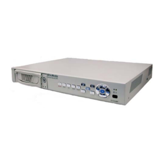
- Page 1 ® AVerMedia EB1004 BAK Real-time Security DVR Operations Manual P/N: 300AABLP MADE IN TAIWAN...
-
Page 2: Fcc Notice
C O P Y R I G H T © 2004 by AVerMedia TECHNOLOGIES, Inc. All rights reserved. No part of this publication may be reproduced, transmitted, transcribed, stored in a retrieval system, or translated into any language in any form by any means without the written permission of AVerMedia TECHNOLOGIES, Inc. -
Page 3: Table Of Contents
Introduction ...3 Features and Specifications ...3 Front Panel ...4 Back Panel...6 Setting Up the DVR Unit...6 Installing Hard Drives ...6 Install the Hard Drive in a Removable Case...7 Install a Removable Hard Drive Case in a PC (Optional) ...8 Connecting Devices...8 Basic Devices ...8... -
Page 4: Introduction
640 x 224 resolution at 7.5 fps. QUAD mode records video in 320 x 112 resolution and up to 30 fps/25 fps (NTSC/PAL). EB1004 BAK provides a removable rack for installing one hard drive and an internal slot for installing a second hard drive. -
Page 5: Back Panel
The DVR unit allows you to install up to two hard drives (a master and slave drive). Install the master hard drive inside DVR unit and fix it, and put the slave hard drive in a removable hard disk bay as the right picture shows. -
Page 6: Install The Hard Drive In A Removable Case
Connecting Devices At the back panel of the DVR unit, you can connect up to four video cameras, four sensor devices, and one alarm device. You can connect a VGA monitor or a television monitor as a display device. Use a USB cable to connect to a PC if it is necessary. -
Page 7: Optional Devices
Connect the video output of each video camera or composite video source to the CH1 ~ CH4 connectors. • VGA monitor Connect a VGA monitor to the VGA OUT connector of the DVR unit to use as a display for video surveillance and playback. • Power adapter Plug the provided 110V AC or 220V power adapter into the DVR unit's power socket. -
Page 8: Video Recording And Playback
Use the following front panel buttons to select the desired video camera to display in full screen: CH1: Camera 1 CH2: Camera 2 CH3: Camera 3 Note: The recording mode can be selected in the OSD main menu. Video Recording and Playback To record surveillance video: To customize recording settings, press the MENU button and choose the desired recording settings. -
Page 9: Setup Menu
Setup Menu MAIN MENU > CAMERA SELECT 1234 RECORD SCHEDULE RECORD SELECT 1234 RECORD MODE EACH RECORD FRAMERATE + T T T S S S S S T T T T M M M M T T T T T + VIDEO QUALITY NORMAL RECORD SCHEDULE... -
Page 10: Record Select
If you prefer to record video only at certain time schedules within a day, you can choose specific recording hours. If the DVR unit is connected to sensor devices, you can also customize the unit to initiate video recording only when the sensors detect an event. -
Page 11: Sub Menu
Press the SELECT button repeatedly to cycle through these settings: ( T ) For automatic non-stop video recording ( S ) For sensor recording. The DVR unit initiates recording only when the attached sensor devices detect motion from the video cameras. -
Page 12: Vga Setup
PRESS (< , >), THEN(SELECT) PRESS (MENU) TO EXIT Set RESOLUTION and REFRESH RATE based on the supported display mode and refresh rate of the VGA monitor that is connected to the DVR unit. Different monitors support different refresh rates: Resolution... -
Page 13: Hard Drive Setup
This determines the duration of sound (in minutes) that is set off when the alarm device is triggered. CHANNEL1 ~ CHANNEL4 These correspond to the four sets of sensor inputs on the DVR unit. Customize these according to the initial state of the attached sensor devices. There are three states to choose from: NOT INSTALLED : Indicates that the channel does not have a sensor device connected. -
Page 14: Connect To A Pc
Connect to a PC EB1004 BAK provides a convenient tool to trace back the recorded surveillance video, catch specific images and save as AVI files. With the EB-DVR Playback Application, users can play back the surveillance video, catch images and backup all recorded images easily . -
Page 15: Operating Eb-Dvr Playback Application
For users with only one hard disk in EB-DVR unit, there are 2 ways to read the data in the hard drive. One way is to install the hard disk inside the EB-DVR unit and utilize a USB cable to connect both EB-DVR unit and PC. -
Page 16: Free Video Playback
Catch Images and Video WB-DVR Playback Application provides functions to output both dynamic and static images. Users can easily catch a static screen and save it as a BMP file, or save some fragment of recorded video as an AVI file. -
Page 17: Warranty Notice
PC and save the files as AVI files. Warranty Notice LIMITED WARRANTY AVerMedia TECHNOLOGIES, Inc. warrants this product to be free of defects resulting from faulty manufacture or components under the following terms: WARRANTY LENGTH Labor is warranted for (1) one year from the date of purchase.
Need help?
Do you have a question about the EB1004 BAK and is the answer not in the manual?
Questions and answers