Table of Contents
Advertisement
Quick Links
Hardware User's Manual
Megapixel Extendible Network Camera
Product name:
Release Date:
Manual Revision:
Web site:
Email:
0
Hydra Series
PH-100Ah Kit Series
Network Camera (Hydra Series)
2014/6
V1.0
www.brickcom.com
support@brickcom.com
info@brickcom.com
© 2014 Brickcom Corporation. All Rights Reserved
Advertisement
Table of Contents

Related Manuals for Brickcom Hydra Series


Summary of Contents for Brickcom Hydra Series
- Page 1 Hardware User’s Manual Hydra Series Megapixel Extendible Network Camera PH-100Ah Kit Series Product name: Network Camera (Hydra Series) Release Date: 2014/6 Manual Revision: V1.0 Web site: www.brickcom.com support@brickcom.com Email: info@brickcom.com © 2014 Brickcom Corporation. All Rights Reserved...
-
Page 2: Table Of Contents
Table of Contents Before You Use This Product ......................2 FCC Warning ............................3 Regulatory Information ........................4 Package Contents..........................6 Product Comparison .......................... 7 Hydra Network Camera Overview....................8 Device Appearance Description ....................10 LED Behavior ............................. 11 System Requirements........................13 Camera Installation .......................... -
Page 3: Before You Use This Product
Before You Use This Product In many countries, there are laws prohibiting or restricting the use of surveillance devices. This Network Camera is a high-performance, web-ready camera which can be part of a flexible surveillance system. It is the user’s responsibility to ensure that the operation of this camera is legal before installing this unit for its intended use. -
Page 4: Fcc Warning
FCC Warning This device complies with Part 15 of FCC rules. Operation is subject to the following two conditions: (1) This device may not cause harmful interference. (2) This device must accept any interference received, including interference that may cause undesired operations. -
Page 5: Regulatory Information
Regulatory Information Federal Communication Commission Interference Statement This equipment has been tested and found to comply with the limits for a Class B digital device, pursuant to Part 15 of the FCC Rules. These limits are designed to provide reasonable protection against harmful interference in a residential installation. This equipment generates uses and can radiate radio frequency energy and, if not installed and used in accordance with the instructions, may cause harmful interference to radio communications. - Page 6 IMPORTANT NOTE: FCC Radiation Exposure Statement: This equipment complies with FCC radiation exposure limits set forth for an uncontrolled environment. This equipment should be installed and operated with minimum distance 20cm between the radiator & your body. This transmitter must not be co-located or operating in conjunction with any other antenna or transmitter.
-
Page 7: Package Contents
Package Contents Please check to make sure the product package contains all the accessories listed below. Video Box (VB-03) Network Camera (Optional) * PH-100Ah-00 PH-100Ah-01 Product CD Mounting Bracket Warranty Card Screw Bag Easy Installation Guide (*) The actual device and quantity vary with the product’s configuration. -
Page 8: Product Comparison
Product Comparison Model Name Lesns Focal Length Horizontal FOV 57° PH-100Ah-00 Board Lens 3.7mm Hydra Series 100° Ph-100Ah-01 Board Lens 2.3mm... -
Page 9: Hydra Network Camera Overview
Brickcom’s commitment to driving innovation and bringing the best products to the market. The 1st product of the Hydra series is the PH-100Ah Kit. It consists of 1 unit of VB-03 video box and 1 unit of PH-100Ah super mini camera, and has the capability of connecting up to 3 PH-100Ah cameras. - Page 10 Multi-Purpose Monitoring: Up to 3 PH-100Ah cameras can be attached to the VB-03. More Hydra series cameras are coming out to offer the user a variety of choices in the form factor, optics, and imaging capability. Collaborative Monitoring: with up to 3 PH-100Ah cameras attached to the VB-03, the PH-100Ah Kit can not only monitor 3 different places simultaneously, but also monitor a certain place from 3 distinct viewpoints.
-
Page 11: Device Appearance Description
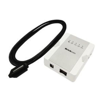
Device Appearance Description < Front & Rear view > Audio out Audio in Status Internet Camera Connected indicator 1 Camera Connected indicator 2 Camera Connected indicator 3 3G dongle USB port Micro SD/SDHC/SDXC Card 2 pairs of DI/DO Camera Port 1 Camera Port 2 Camera Port 3 Power Jack (DC12V) -
Page 12: Led Behavior
LED Behavior Function LED Behavior Description Power Continuous Illumination Normal Operation Power Unlit Power off Status Continuous Illumination Connect to the switch by Ethernet or WiFi 1. Power off Status Unlit 2. No connection Status Blinking Data Transmission via Ethernet Internet Continuous Illumination Connect to Internet... - Page 13 operation. NOTE - By restoring the camera, all settings will be restored to the factory default settings. Micro SD/SDHC/SDXC Card Capacity The network camera is compatible with Micro SD/SDHC/SDXC (Maximum 64GB) card.
-
Page 14: System Requirements
System Requirements Operating System: Microsoft Windows, ONVIF Supported NVR system CPU: Pentium 3GHz or faster Network Interface: 10/100Mbps Network interface card must be installed Web Browser: Microsoft Internet Explorer, Firefox, Chrome Audio: The audio function will not work if a sound card is not installed in the PC. Audio may be interrupted depending on the network traffic. -
Page 15: Camera Installation
Camera Installation Step 1. Power and Ethernet Connection a. Power on the camera with PoE switch: Use an Ethernet cable to connect VB-03 to the PoE switch. PoE Switch b. Power on the camera with PoE injector: i. Use an Ethernet cable to connect VB-03 to a PoE injector. ii. - Page 16 c. Power on the camera with DC12V 1A power adaptor. Router/ Computer/ NVR/ Switch Step 2. Terminal I/O Block Adaptor Pin Definition (from left to right) 1. Ground 2. Digital Input 3. Digital Output 4. Power +12V 5. Ground 6. Digital Input 7.
- Page 17 VB-03, and make sure the corresponding LED indicators are lit. The Hydra series camera offers simultaneous dual views with 2 lens modules connected, and simultaneous triple views with 3 lens modules connected.
-
Page 18: Easyconfig Installation
EasyConfig Installation Insert the Installation CD into the CD-ROM driver. Run Auto-Run Tool directly from the CD-ROM to start the installation. When installing the Brickcom software kit at the first time, select a desired language for the interface. The available languages are listed in the scroll box. - Page 19 In the Install Shield Wizard dialog box, click <Next> to continue. Read the End-User License Agreement and check the option <I accept the terms of the license agreement>. Then, click <Next> to continue.
- Page 20 Click <Change> to change the appointed folder where the installation and program files will be stored. Then, click <Next> to continue. Select to create shortcuts and click <Next> to continue.
- Page 21 Click to launch the application, and click <Finish> to complete the installation and return to Shield Wizard dialog box. When launching the PC-NVR program, please refer to the PC-NVR’s user manual.
-
Page 22: Launch Easyconfig
If Custom Setup type was used in the software installation but an EasyConfig icon was not installed on the desktop, the program will be installed under “C:\Program Files\Brickcom\EasyConfig” unless the program was saved to a preferred directory. NOTE - Check <Skip the hardware installation guide> to skip checking the hardware connection. - Page 23 Click <Start> to continue. The program will automatically search for the camera in the intranet.
- Page 25 Select either <Simple Mode> or <Professional Mode> to obtain the camera’s IP settings. If <Simple Mode> is selected, EasyConfig will set up the connection automatically. If <Professional Mode> is selected, the user will need to configure the IP settings manually. There may be many cameras in the local network.
- Page 26 Enter the username and password of the camera. For the first-time use, the default username and password are “admin/admin.” To configure the IP address settings, select either <Settings remain the same>, <Automatically obtain an IP Address (DHCP)> or <Set IP Address configuration manually>.
- Page 27 Otherwise, this window will not be shown. *If desired, click <Skip> to skip this setting. EasyLink is a unique Brickcom function which allows users to assign a unique EasyLink name to their network camera’s IP address. There is no need to configure the router to open up ports or...
- Page 28 remember hard-to-memorize IP addresses. Users can log onto [uniqueEasyLinkname].mybrickcom.com to view the camera’s web GUI and Live View. Enter a unique EasyLink name whose length must be between 5-32 characters. When finished, click the arrow button to continue. When the IP address settings have been configured, the screen will either display a successful or failed connection message.
- Page 29 If “DHCP IP address settings” was selected, the failure window will be displayed as below. If <Static IP address settings> was selected, the failure window will be displayed as above. If the connection was successful, the user will see the message: <Congratulations.
- Page 30 When this window is displayed, click <BRC64> to start the BRC64 program, <Live View> to view the live video from the connected IP camera, or <X> in the top right corner of the screen to close the installation window. If the user starts the BRC64 program, please refer to PC-NVR’s user manual.
-
Page 31: Accessing The Network Camera
Accessing the Network Camera Check Network Settings The camera can be connected either before or immediately after the software installation. The Administrator should complete the network settings on the configuration page, including entering the correct subnet mask, IP address of gateway, and DNS. -
Page 32: Viewing Video Streams With Internet Explorer
Viewing Video Streams with Internet Explorer Step 1. Check the Video Stream Settings On the camera's web UI, please go to Configuration → Camera/Video/Audio → Video, and you will find the stream 1, stream 2, and stream 3 settings. Please make sure the video stream corresponding to the connected lens module is enabled. - Page 33 Viewing Video Streams with BRC64 Step 1. Launch BRC64 Double click to launch BRC64, or click it on the on the Windows desktop program menu. ○ i Please make sure the version of BRC64 is v1.2.4.144 or above. Step 2. Search for the Camera Click on the control panel to start searching for the cameras on the LAN.
- Page 34 Step 3. View 3 Streams Simultaneously For each video stream you want to view, please select the camera item on the control panel. Then, drag and drop it to the video matrix for live view.
- Page 35 If the lens module hasn’t been pluggged in the VB-03, the “Reconnecting” message will be shown, and you won’t be able to view the image of this lens module. Please check if the lens modules are successfully plugged in the VB-03.
Need help?
Do you have a question about the Hydra Series and is the answer not in the manual?
Questions and answers