
Related Manuals for Moxa Technologies DA-685 Series


Summary of Contents for Moxa Technologies DA-685 Series
- Page 1 DA-685 Series Embedded Computer Hardware Manual First Edition, July 2012 www.moxa.com/product © 2012 Moxa Inc. All rights reserved. Reproduction without permission is prohibited.
-
Page 2: Copyright Notice
DA-685 Series Embedded Computer User’s Manual The software described in this manual is furnished under a license agreement and may be used only in accordance with the terms of that agreement. Copyright Notice Copyright ©2012 Moxa Inc. All rights reserved. -
Page 3: Table Of Contents
Table of Contents Introduction ............................1-1 Overview ............................1-2 Model Descriptions and Package Checklist ....................1-2 Appearance ............................1-2 Features ............................1-3 Hardware Block Diagram ........................1-4 Hardware Specifications ........................1-4 Hardware Installation ........................2-1 Placement Options ..........................2-2 Desktop ............................. 2-2 Rack mounting .......................... -
Page 4: Introduction
Introduction Thank you for purchasing the Moxa DA-685 series x86 industrial ready-to-run substation computer. This manual introduces the hardware installation, connector interfaces, and BIOS setup of the DA-685. For software configuration and management, please refer to the user’s manual for your operating system. -
Page 5: Overview
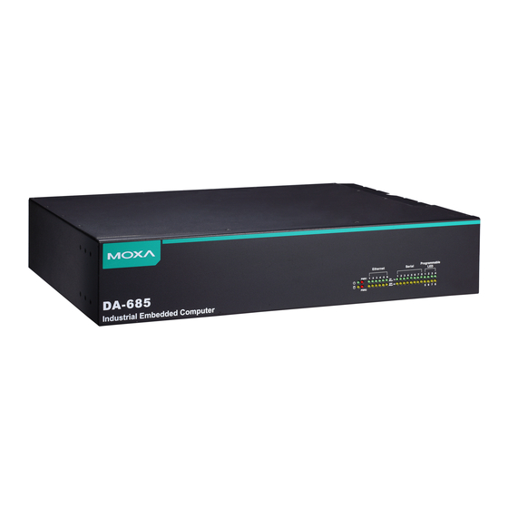
Introduction Overview DA-685 industrial computers excel in a wide array of substation automation roles. The DA-685 Series is an x86 platform and features VGA, 6 Gigabit Ethernet ports, 2 selectable RS-232/422/485 ports, 6 RS-485 serial ports, CompactFlash, and 2 USB 2.0 interfaces. The computers come in a 19-inch/2U chassis with an Intel Atom processor, giving them the punch needed to handle demanding industrial tasks but at an economical price and without consuming a lot of power. -
Page 6: Features
DA-683 Series Introduction Rear View Dimensions Features The DA-685 computer has the following features: Intel Atom D510 1.66 GHz processor 1 DDR2 SODIMM sockets supporting DDR2 667 up to 2 GB (max.) 6 10/100/1000 Mbps Ethernet ports 2 selectable RS-232/422/485 DB9 (male) ports ... -
Page 7: Hardware Block Diagram
DA-683 Series Introduction ATTENTION Refer to the “Non-standard Baudrates” section for instructions on how to calculate which baudrates are supported. Hardware Block Diagram Hardware Specifications Computer CPU: Intel Atom D510 1.66 GHz processor OS: Linux, Windows 7, Windows XP Professional, or Windows Embedded Standard 2009 (must be installed by the user) System Chipset: Intel Pineview-D + ICH8M BIOS: 16 Mbit Flash BIOS, PCI Plug &... - Page 8 DA-683 Series Introduction Ethernet Interface LAN: 6 auto-sensing 10/100/1000 Mbps Gigabit ports Magnetic Isolation Protection: 1.5 KV built-in Serial Interface Serial Standards: • 2 selectable RS-232/422/485 ports (DB9 male) • 6 2-wire RS-485 ports (terminal block) Serial Signals RS-232: TxD, RxD, DTR, DSR, RTS, CTS, DCD, GND, RI RS-422: TxD+, TxD-, RxD+, RxD-, GND 4-wire RS-485: TxD+, TxD-, RxD+, RxD-, GND 2-wire RS-485: Data+, Data-, GND...
-
Page 9: Hardware Installation
Hardware Installation The DA-685 Series of electrical substation computers are compact and rugged, making them suitable for any industrial application that requires EMC Level 4 compliance. The LED indicators allow users to monitor performance and identify trouble spots quickly, and multiple ports are provided for connecting a variety of different devices. -
Page 10: Placement Options
DA-683 Series Hardware Installation Placement Options Desktop Place your DA-685 on a clean, flat, well-ventilated desktop. For better ventilation, leave some space between the DA-685 and other equipment. Do not place equipment or objects on top of the DA-685, as this might damage the computer’s internal components. - Page 11 DA-683 Series Hardware Installation Step 2: Installing a rackmount handle (optional) to a rack ear Use 2 FMSM5X10 screws to attach the rackmount handle to the ear, as shown. Step 3: Installing the rack ears to the DA-685 For each side panel of the DA-685, use 6 FMSM4X6 screws to affix the ear to the DA-685, as shown below. Step 4: Installing the DA-685 to a rack Gently slide the DA-685 onto the rack and use the mounting screws provided by the rack supplier to affix the DA-685 in place.
-
Page 12: Wiring Requirements
DA-683 Series Hardware Installation As a final check, make sure that the computer is snugly affixed in place. Wiring Requirements The following common safety precautions should be observed before installing any electronic device: • Strive to use separate, non-intersecting paths to route power and networking wires. If power wiring and device wiring paths must cross, make sure the wires are perpendicular at the intersection point. -
Page 13: Connecting The Power
DA-683 Series Hardware Installation ATTENTION Safety First! Be sure to disconnect the power cord before installing and/or wiring your device. Caution! High Electrical Current! Calculate the maximum possible current for each power wire and common wire. Observe all electrical codes dictating the maximum current allowable for each wire size. -
Page 14: Wiring The Power Inputs
DA-683 Series Hardware Installation Wiring the Power Inputs... -
Page 15: Power Input Wiring Description
DA-683 Series Hardware Installation Power Input Wiring Description Read the following section for a detailed power input wiring description. Terminal Number Description Note PWR1 Line + is connected, or to the Line terminal PWR1 Line for the AC power source. PWR1 Neutral –... -
Page 16: Front Panel Led
DA-683 Series Hardware Installation When finished, press the Power Switch button to start the system. It will take about 30 to 60 seconds for your operating system to boot up. Front Panel LED There are 40 LED indicators on the front panel. Information about each LED is given in the following table. The additional ports LEDs, named Port 1 and Port 2 are temporarily reserved for future use. -
Page 17: Connecting To A Display
DA-683 Series Hardware Installation Connecting to a Display The DA-685 comes with a D-Sub 15-pin female connector on the front panel to connect a VGA monitor. To ensure that the monitor image remains clear, be sure to tighten the monitor cable after connecting it to the DA-685 computer. -
Page 18: Connecting Usb Devices
DA-683 Series Hardware Installation ATTENTION Please note that without the Y-type cable, the PS/2 connector on the DA-685 can only work with a PS/2 keyboard. A PS/2 mouse will not function when directly connected to the PS/2 connector on the DA-685 embedded computer. -
Page 19: Lan Ports
DA-683 Series Hardware Installation The pin assignments for RS-485-2w serial ports are show in the following table: Terminal Block Port RS-485-2w Pinouts RS-485-2W – – DataB(+) DataA(-) LAN Ports The DA-685 has 6 10/100/1000 Mbps LAN ports. When the cable is properly connected, the LEDs on the front panel will glow to indicate a proper connection. -
Page 20: Upgrading The Memory Module
DA-683 Series Hardware Installation Upgrading the Memory Module The DA-685 embedded computer supports one 200-pin DDR2 667 SODIMM module of up to 2 GB. One DDR2 SDRAM memory module is pre-installed. To upgrade the DDR2 SDRAM memory module, follow these instructions: 1. -
Page 21: Installing A Compactflash Card
DA-683 Series Hardware Installation 6. Push the memory all the way down to complete installation. Installing a CompactFlash Card The DA-685 embedded computer comes with a CompactFlash socket. To insert a CompactFlash card, follow these instructions. 1. Disconnect the DA-685 from its power source. 2. -
Page 22: Installing A Sata Storage Drive
DA-683 Series Hardware Installation Installing a SATA Storage Drive The DA-685 embedded computer features a single SATA connector for SATA storage drives. To install a 2.5-inch SATA storage drive (SSD or HDD) a DA-685 storage drive mounting assembly must be acquired (it is not included in the basic DA-695 packaging). -
Page 23: Upgrading A Dom
DA-683 Series Hardware Installation 6. Connect the power cable and SATA cable to the motherboard, as follows: ATTENTION The SATA storage drive mounting assembly – which includes the SATA data and power cables – does not ship with the basic models of the DA-685 embedded computer. For purchasing information, please contact Moxa. Upgrading a DOM The DA-685 comes with an IDE-based DOM in which the operating system has been installed. -
Page 24: Bios Setup
BIOS Setup This chapter describes the BIOS settings of the DA-685 computer. The BIOS is a set of input/output control routines for peripherals. The BIOS is used to initialize basic peripherals and loads the operating system. The BIOS setup allows the user to modify the system configurations of these basic input/output peripherals. All of the configurations will be stored in the NVRAM (flash memory), which retains the system information after system reboots or the power is removed. - Page 25 DA-683 Series BIOS Setup Entering the BIOS Setup Utility To enter the BIOS setup utility, press the “F2” key while the system is booting up. The main BIOS Setup screen will appear. A basic description of each function key is listed at the bottom of the screen. Refer to these descriptions to learn how to use them.
-
Page 26: Advanced Settings
DA-683 Series BIOS Setup Modifying BIOS Settings Navigate the BIOS menus using the arrow keys; up (↑) and down (↓) arrows navigate the menu, while left (←) and right (→) arrows will open or close sub-menus from entries marked with a triangle (▲) at the beginning of the line. -
Page 27: Peripheral Configuration
DA-683 Series BIOS Setup Peripheral Configuration The Debug Port item under Peripheral Configuration allows you to select an alternate debugging interrupt. Please note that this should be used only by programmers who are familiar with debugging. Options: 2E8/IRQ6, Disabled (default) IDE Configuration This item allows you to configure the storage drive controllers. -
Page 28: Video Configuration
DA-683 Series BIOS Setup Channel Master 1 to 3 This setting displays the storage devices installed on the computer’s master bus. These storage devices may be DOMs, HDDs, SSDs, or a CF card. Channel Slave 1 to 3 This setting displays storage devices installed on the computer’s slave bus. These storage drives may be DOMs, HDDs, SSDs, or a CF card. -
Page 29: Usb Configuration
DA-683 Series BIOS Setup USB Configuration This item allows you to turn USB Legacy mode on or off. USB Legacy allows older USB devices to be accessed from the earliest boot initialization, and/or DOS. Options: Enabled (default), Disabled ACPI Table/Features Control This item allows you to configure FACP and HPET functions. -
Page 30: Hardware Monitor
DA-683 Series BIOS Setup FACP – RTC S4 Wakeup This item allows you to enable RTC wakeup, so the computer may pull itself out of sleep or hibernation mode to perform specified tasks at a certain time each day. Options: Enabled (default), Disabled HPET –... -
Page 31: Security Settings
DA-683 Series BIOS Setup Security Settings The section allows users to configure security settings like a system supervisor password and user password. Set Supervisor Password This item allows you to set the supervisor password. Select and then enter the password, and then confirm the password again. -
Page 32: Power Settings
DA-683 Series BIOS Setup Power Settings The section allows users to configure power settings. Advanced CPU Control Thermal Mode This item enables Intel’s thermal throttling 1 technology in the CPU; it functions as a temperature trip that will throttle the CPU (and thereby decrease performance) when a certain temperature is reached. Enabling this function allows you to configure the thermal control circuit in the operating system userspace. -
Page 33: Boot Settings
DA-683 Series BIOS Setup ACPI S3 This item allows you to enable/disable Processor Performance States (P-States) function; this technology is primarily intended for power conservation on laptops. By default, it is enabled. Options: Disabled, Enabled (default). PWRON After PWR-Fail (Power on after Power Fail) This item allows you to configure the computer to turn itself back on after a power failure. -
Page 34: Quick Boot
DA-683 Series BIOS Setup UEFI Boot This item allows you to enable/disable the Unified Extensible Firmware Interface, which allows for remote diagnostics and repair of computers even without an operating system. Users who are concerned about safety or ownership issues may disable it. Options: Enabled (default), Disabled Quick Boot This item allows you to enable/disable quick book function to reduce OS loading times. -
Page 35: Exit Settings
DA-683 Series BIOS Setup Boot Type Order This item allows you to select the order in which the computer will search storage devices for bootable images; the highest device on the list will be searched first, then the second, and so on until the computer finds a bootable image. -
Page 36: Load Defaults Setting
DA-683 Series BIOS Setup Load Defaults Setting This item resets the entire BIOS to factory default values. Options: Yes (default), No Load Custom Defaults This item loads custom defaults across the entire BIOS. Options: Yes (default), No Save Custom Defaults This item saves the current BIOS settings as the new custom defaults. - Page 37 DA-683 Series BIOS Setup ATTENTION We suggest you use a USB drive with under 2 GB in disk space, as larger USB drives may not support the FAT file format and will consequently fail to boot. Step 2: Prepare the Upgrade File. You must use the BIOS upgrade installation file to upgrade the BIOS.
- Page 38 DA-683 Series BIOS Setup 3. Once the computer boots, a DOS screen will appear. Go to the directory where the upgrade file is located. For example, if the upgrade file is stored in the DA685 folder, type: #:/cd DA685 C:\ cd DA685 4.
-
Page 39: Safety Installation Instructions
Safety Installation Instructions A. RTC Battery Warning CAUTION: There is a risk of explosion if battery is replaced by an incorrect type. Dispose of used batteries according to the instructions. B. Fuse Warning CAUTION: For continued protection against fire, replace only with same type and rating of fuse. C. -
Page 40: Regulatory Statement Approval
Regulatory Statement Approval This device complies with part 15 of the FCC Rules. Operation is subject to the following two conditions: (1) This device may not cause harmful interference, and (2) this device must accept any interference received, including interference that may cause undesired operation.
Need help?
Do you have a question about the DA-685 Series and is the answer not in the manual?
Questions and answers