
Related Manuals for Moxa Technologies DA-682A Series


Summary of Contents for Moxa Technologies DA-682A Series
- Page 1 DA-682A Series Embedded Computer Hardware Manual Third Edition, May 2015 www.moxa.com/product © 2015 Moxa Inc. All rights reserved.
- Page 2 DA-682A Series Embedded Computer Hardware Manual The software described in this manual is furnished under a license agreement and may be used only in accordance with the terms of that agreement. Copyright Notice © 2015 Moxa Inc. All rights reserved.
-
Page 3: Table Of Contents
Table of Contents Introduction ............................1-1 Overview ............................1-2 Model Descriptions and Package Checklist ....................1-2 Appearance ............................1-3 Dimensions ............................1-4 Features ............................1-4 Hardware Block Diagram ........................1-5 DA-682A Basic System......................... 1-5 Hardware Specifications ........................1-5 Basic Systems ..........................1-5 Expansion Modules .......................... -
Page 4: Introduction
Introduction Thank you for purchasing a Moxa DA-682A Series ready-to-run industrial computer. This manual introduces the hardware installation, connector interfaces and BIOS setup of the DA-682A. For software configuration and management, please refer to the user’s manual for your operating system. -
Page 5: Overview
Introduction Overview The DA-682A series of computers are x86 platforms in a standard 19 inch 2U rack-mountable case, with VGA output, 6 gigabit Ethernet ports, a CompactFlash socket, four USB ports, and two PCI slots that accept DA Series expansion modules. -
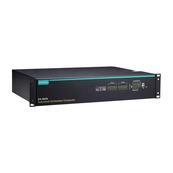
Page 6: Appearance
DA-682A Series Hardware Introduction Optional Expansion Modules: • DA-SP08-I-DB: 8-port RS-232/422/485 serial port module with isolation protection, DB9 connectors • DA-SP08-DB: 8-port RS-232/422/485 serial port module, DB9 connectors • DA-SP08-I-TB: 8-port RS-232/422/485 serial port module with isolation protection, terminal block connector •... -
Page 7: Dimensions
DA-682A Series Hardware Introduction Dimensions Features The DA-682A computer has the following features: generation Intel core processors (Sandy Bridge) Built-in DDR3 SDRAM and industrial DOM 6 Gigabit Ethernet ports for network redundancy 2 PCI expansion slots for expansion modules ... -
Page 8: Hardware Block Diagram
DA-682A Series Hardware Introduction Hardware Block Diagram DA-682A Basic System Hardware Specifications Basic Systems Computer CPU: 2nd generation Intel core processors (Sandy Bridge) • Intel Celeron 827E, 1.4 GHz single core processor • Intel Celeron 847E, 1.1 GHz dual core processor •... - Page 9 DA-682A Series Hardware Introduction Display Graphics Controller: Integrated graphics with built-in Intel 915GME, and built-in Intel Extreme Graphics 2 technology Display Memory: Dynamic video memory (shares up to 32 MB of system memory) Display Interface: CRT Interface for VGA output (DB15 female connector)
-
Page 10: Expansion Modules
DA-682A Series Hardware Introduction Expansion Modules Software-Selectable Serial Ports DA-SP08-I-DB DA-SP08-DB DA-SP08-I-TB DA-SP38-I-TB Serial Interface Number of Ports RS-232/422/485 x 8 RS-422/485 x 8 Serial Standards RS-232/422/485, software-selectable RS-422/485 Connector DB9 male DB9 male 5-pin terminal block Protection 15 KV ESD and 2... -
Page 11: Non-Standard Baudrates
DA-682A Series Hardware Introduction Non-standard Baudrates Moxa’s UART ASIC, which is used for both the DA-SP08-I-DB and DA-SP08-I-TB serial expansion modules, supports most non-standard baudrates in the range 50 bps to 921.6 Kbps. In fact, supported baudrates are much denser towards the lower values. For example, no baudrates are supported between the integers 5320 and 5323, but 49 baudrates are supported between the integers 387 and 388. -
Page 12: Hardware Installation
Hardware Installation The DA-682A Series of embedded computers are compact and rugged, making them suitable for industrial applications. The LED indicators allow users to monitor performance and identify trouble spots quickly, and multiple ports are provided for connecting a variety of different devices. The DA-682A embedded computers come with a reliable and stable hardware platform that lets you devote the bulk of your time to application development. -
Page 13: Placement Options
DA-682A Series Hardware Hardware Installation Placement Options Desktop Place your DA-682A on a clean, flat, well-ventilated desktop. For better ventilation, leave some space between the DA-682A and other equipment. Do not place equipment or objects on top of the DA-682A, as this might damage the computer’s internal components. - Page 14 DA-682A Series Hardware Hardware Installation Step 2: Installing the handles Use 4 FMSM5X10 screws (2 for each side) to attach the handles to the brackets. Step 3: Installing the brackets Use 6 FMSM4X6 screws to attach a bracket to one side of the DA-682A. Repeat this procedure on the other side.
-
Page 15: Wiring Requirements
DA-682A Series Hardware Hardware Installation As a final check, make sure that the four screws are firmly attached to the rack. screws screws Wiring Requirements The following common safety precautions should be observed before installing any electronic device: • Keep power wires and communications/signals wires in separate paths. If power and communications/signal wires must cross paths, make sure the wires are perpendicular at the intersection point. -
Page 16: Connecting The Power
DA-682A Series Hardware Hardware Installation Connecting the Power To power on the DA-682A embedded computer, connect the power line to the DA-682A’s AC power connector (located on the right side of the rear panel) using the power cord shipped with the product, and then turn on the power switch. -
Page 17: Front Panel Led
DA-682A Series Hardware Hardware Installation Front Panel LED There are 58 LED indicators on the front panel, and 2 on the rear panel. Information about each LED is given in the following table. Color Description Green Power is on Power... -
Page 18: Connecting To A Display
DA-682A Series Hardware Hardware Installation Connecting to a Display Your DA-682A embedded computer comes with a D-Sub 15-pin female connector to connect to the VGA monitor. Be sure to remove the power before you connect or disconnect the monitor cable. -
Page 19: Connecting Usb Devices
DA-682A Series Hardware Hardware Installation Connecting USB Devices The DA-682A embedded computer has four USB 2.0 ports, with two ports on the front panel and the other two on the rear panel. All of the ports are UHCI, Rev 2.0 compliant and support Plug & Play and hot swapping. These ports can be used to connect USB devices, such as a keyboard, mouse, USB flash disk, and USB CD-ROM. -
Page 20: Gigabit Lan Ports
DA-682A Series Hardware Hardware Installation Gigabit LAN Ports The DA-682A Basic System has 6 Gigabit LAN ports. When the cable is properly connected, the LEDs on the RJ45 connectors will glow to indicate a proper connection. 10/100 Mbps 1000 Mbps... -
Page 21: Upgrading The Memory Module
DA-682A Series Hardware Hardware Installation Upgrading the Memory Module The DA-682A embedded computer supports one DDR3 1066/1333 SODIMM module, up to 4 GB. One DDR3 SDRAM memory module is installed at the factory. To upgrade the SDRAM memory module, follow these instructions: 1. -
Page 22: Installing A Compactflash Card
DA-682A Series Hardware Hardware Installation Installing a CompactFlash Card The DA-682A embedded computer comes with a CompactFlash socket. To insert a CompactFlash card, follow these instructions. 1. Disconnect the DA-682A from its power source. 2. Unfasten the screws on the back of the computer, and then take off the upper cover. -
Page 23: Installing A Disk On Module (Dom)
DA-682A Series Hardware Hardware Installation Installing a Disk on Module (DOM) The DA-682A stores its operating system on a disk-on-module (DOM) that is pre-installed inside the computer. Users can install their own DOM, if so desired. 1. Disconnect the DA-682A from its power source. - Page 24 DA-682A Series Hardware Hardware Installation Step 1: Connect the SATA cables to the hard drive/drives. Step 2: Place the hard drive/drives on the bracket. Make sure they are placed in the correct direction. Step 3: Fasten the hard drives to the brackets as shown (single on left, double on right).
-
Page 25: Installing And Removing Expansion Modules
DA-682A Series Hardware Hardware Installation Step 5: Place and fasten the bracket with the screws. Step 6: Connect the cables to the appropriate jacks (power at top, data below). Single Disk Dual Disks Installing and Removing Expansion Modules The DA-682A embedded computer has two slots for DA expansion modules. There is no primary or secondary slot: modules may be installed in either on slot A or slot B, as the user wishes. -
Page 26: Sp08-I-Db/Da-Sp08-Db/Da-Sp08-I-Emc4-Db Serial Expansion Modules
DA-682A Series Hardware Hardware Installation DA-SP08-I-DB/DA-SP08-DB/DA-SP08-I-EMC4- DB Serial Expansion Modules The DA-SP08-I-DB, DA-SP08-I-EMC4-DB, and DA-SP08-DB serial expansion modules have 8 software-selectable serial ports with DB9 connectors. The DA-SP08-I-DB and DA-SP08-I-EMC4-DB support 2 kV isolation protection for all signals. In addition, the DA-SP08-I-EMC4-DB is able to withstand EMC level 4 interference. -
Page 27: Da-Ln04-Rj Lan Expansion Module
DA-682A Series Hardware Hardware Installation DA-LN04-RJ LAN Expansion Module The DA-LN04-RJ LAN expansion module has 4 10/100 Mbps Ethernet ports with RJ45 connectors. The pin assignments for the ports are shown in the following table: Pin No. Signal Definition There are two LEDs on each RJ45 port for indicating the status of the port. -
Page 28: Bios Setup
BIOS Setup This chapter describes the BIOS settings of the DA-682A computer. The BIOS is a set of input/output control routines for peripherals. The BIOS is used to initialize system peripherals before the operating system is loaded. The BIOS setup allows the user to modify the system configurations of these peripherals’ basic input/output. The following topics are covered in this chapter: ... -
Page 29: Entering The Bios Setup
DA-682A Series Hardware BIOS Setup Entering the BIOS Setup To enter the BIOS setup utility, press the “F2” key while the system is booting up. The main BIOS Setup screen will appear. Four options will be available: Continue: Continue to boot up... -
Page 30: Main Information
DA-682A Series Hardware BIOS Setup The BIOS configuration screen will be shown when you enter SCU option. Refer to the following figure. Please note that the information for Processor Type will vary depending on the different models that you purchase. -
Page 31: Boot Configuration
DA-682A Series Hardware BIOS Setup Boot Configuration This item allows users to configure the default value of Numlock. Option: On (default), Off. HDC Configuration The host drive controller may be configured for IDE (legacy default) or AHCI mode. When the legacy IDE mode is selected, the following screen will appear. -
Page 32: Video Configuration
DA-682A Series Hardware BIOS Setup Serial ATA Port 0 to 3 This setting allows the user to display information about the installed drives. AHCI SALP Please note that AHCI SALP will only appear when AHCI mode is selected. This item allows you to enable aggressive link power management (SALP) in AHCI. -
Page 33: Chipset Configuration
DA-682A Series Hardware BIOS Setup IGD—DVMT Pre-Allocated This item allows you to configure pre-allocated memory capacity for the IGD. Pre-allocated graphics memory is invisible to the operating system. Options: 64 MB (default), 32 MB, 96 MB, 128 MB, 256 MB, 512 MB DVMT is a BIOS solution where “the optimum amount of memory is dynamically allocated and de-allocated as... -
Page 34: Hardware Monitor
DA-682A Series Hardware BIOS Setup Hardware Monitor This item allows you to view stats like CPU and system temperature, voltage levels, and other chipset information. Please note that the voltage values will vary depending on the different models, and there will be 5% tolerance for the temperature values. -
Page 35: Power Settings
DA-682A Series Hardware BIOS Setup Power Settings The section allows users to configure power settings. Turbo Mode This item allows users to determine whether to enable the Intel CPU Turbo Boost technology. Options: Enabled (default), Disable. Please note that this item is only available on the DA-682A-C7, DA-682A-C7-LX, and DA-682A-C7-W7E models. -
Page 36: Boot Settings
DA-682A Series Hardware BIOS Setup Boot Settings The section allows users to configure boot settings. Boot Type This item allows you to enable/disable quick boot function. Options: Dual Boot Type (default), Legacy Boot Type, UEFI Boot Type. PXE Boot to LAN This item allows you to enable/disable PXE boot to LAN function. -
Page 37: Legacy
DA-682A Series Hardware BIOS Setup Legacy Normal Boot Menu This item allows you to configure the boot menu. Options: Normal (default), Advance Boot Type Order This item allows you to select the boot order. Use +/F5 (move up) or -/F6 (move down) to change values. -
Page 38: Load Optimal Defaults
DA-682A Series Hardware BIOS Setup Load Optimal Defaults This item allows you to revert to the factory default BIOS values. Options: Yes (default), No Load Custom Defaults This item allows you to load custom default values for the BIOS settings. - Page 39 DA-682A Series Hardware BIOS Setup 1. Start Rufus and select the USB device that you want to use as a bootable disk from the Device drop-down list. 2. Select MBR partition scheme for BIOS or UEFI computers to boot from a legacy BIOS or UEFI.
- Page 40 DA-682A Series Hardware BIOS Setup 3. When boot up finishes, DOS screen will show up. Go to the directory where the upgrade file is located. For example, if the upgrade file is stored in the DA682A folder, type cd DA682A C:\cd DA682A 4.
-
Page 41: Safety Installation Instructions
Safety Installation Instructions A. RTC Battery Warning CAUTION: There is a risk of explosion if battery is replaced by an incorrect type. Dispose of used batteries according to the instructions. B. Fuse Warning CAUTION: For continued protection against fire, replace only with same type and rating of fuse. C.
Need help?
Do you have a question about the DA-682A Series and is the answer not in the manual?
Questions and answers