
Related Manuals for Moxa Technologies DA-682 Series


Summary of Contents for Moxa Technologies DA-682 Series
- Page 1 DA-682 Series Embedded Computer Hardware User’s Manual First Edition, May 2008 www.moxa.com/product © 2008 Moxa Inc., all rights reserved. Reproduction without permission is prohibited.
-
Page 2: Copyright Notice
DA-682 Series Embedded Computer Hardware User’s Manual Any software described in this manual is furnished under a license agreement and may be used only in accordance with the terms of that agreement. Copyright Notice Copyright © 2008 Moxa Inc. All rights reserved. -
Page 3: Table Of Contents
Table of Contents Chapter 1 Introduction ....................1-1 Overview..........................1-2 Model Descriptions and Package Checklist................1-2 Appearance ..........................1-3 Dimensions ..........................1-4 Features............................ 1-4 Hardware Block Diagram ......................1-5 DA-682 Basic System ....................1-5 DA-SP08-I-DB Serial Port Expansion Module............1-6 DA-LN04-RJ LAN Port Expansion Module .............. 1-6 Hardware Specifications ...................... - Page 4 OnChip IDE Device ....................3-10 Onboard Device......................3-11 Onboard GigaLan Control..................3-12 Onboard I/O Chip Setup................... 3-12 Power ............................. 3-13 Wake Up Control...................... 3-13 Hardware Monitor........................3-15 Load Defaults......................... 3-15 Exiting the BIOS Setup......................3-16 Upgrading the BIOS ......................3-17 Appendix A Safety Installation Instructions..............
-
Page 5: Chapter 1 Introduction
Introduction Chapter 1 Thank you for purchasing a Moxa DA-682 Series X86-based industrial ready-to-run embedded computer. The DA-682 computers come pre-installed with one of three embedded operating systems: • DA-682-CE: Windows CE 6.0 • DA-682-LX: Linux • DA-682-XPE: Windows XP Embedded This manual introduces the hardware installation, connector interfaces and BIOS setup of the DA-682. -
Page 6: Overview
Introduction Overview The Moxa DA-682 Series of X86-based rackmount embedded computers are designed for industrial data acquisition applications. The state-of-art 2 expansion module design provides greater flexibility by allowing combinations of up to 16 RS-232/422/485 serial ports or up to 4+8 Ethernet ports. -
Page 7: Appearance
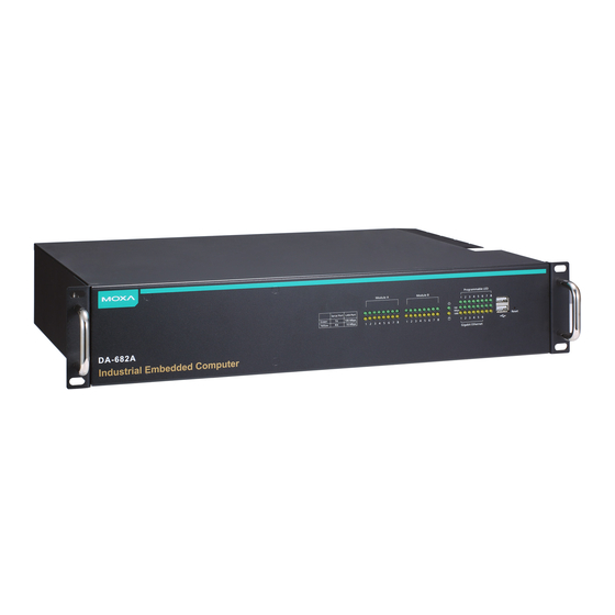
DA-682 Series Hardware User’s Manual Introduction ATTENTION Additional expansion modules are currently under development. Appearance Front View Serial Port Serial Port LED x 8 LED x 8 Ethernet LED x 4 Reset Button DA-682 USB 2.0 Host x 2 Industrial Embedded Computer... -
Page 8: Dimensions
DA-682 Series Hardware User’s Manual Introduction Dimensions 253 mm (9.96 in) 440 mm (17.32 in) DA-682 Industrial Embedded Computer 90 mm Gigabit Ethernet Module B Module A (3.54 in) 100 Mbps 1000 Mbps Serial Port LAN Port Green 100 Mbps... -
Page 9: Hardware Block Diagram
DA-682 Series Hardware User’s Manual Introduction Features supported by expansion modules: 8 or 16 software selectable RS-232/422/485 serial ports, with or without isolation protection Serial port baudrates from 50 to 921.6 Kbps, with support for most non-standard baudrates in this range... -
Page 10: Da-Sp08-I-Db Serial Port Expansion Module
DA-682 Series Hardware User’s Manual Introduction DA-SP08-I-DB Serial Port Expansion Module PCI Bus to DA-682 Basic System Moxa UART ASIC Isolation Circuit DB9 Connector RS-232/422/485 DA-LN04-RJ LAN Port Expansion Module PCI Bus to DA-682 Basic System PCI Bridge Realtek Realtek... -
Page 11: Hardware Specifications
DA-682 Series Hardware User’s Manual Introduction Hardware Specifications DA-682 series embedded computers support peripheral expansion through two expansion slots located on the DA-682 Basic System. Basic Systems DA-682-CE DA-682-LX DA-682-XPE Computer Intel Celeron M 1 GHz processor OS (pre-installed) WinCE 6.0 Linux 2.6... - Page 12 DA-682 Series Hardware User’s Manual Introduction Serial Communication Parameters Data Bits 5, 6, 7, 8 Stop Bits 1, 1.5, 2 Parity None, Even, Odd, Space, Mark Flow Control RTS/CTS, XON/XOFF, ADDC™ (automatic data direction control) for RS-485 Baudrate 50 bps to 921.6 Kbps (non-standard baudrates supported; see user's...
-
Page 13: Serial Port Expansion Modules
DA-682 Series Hardware User’s Manual Introduction Warranty Warranty Period 5 years Details See www.moxa.com/warranty Serial Port Expansion Modules DA-SP08-I-DB DA-SP08-DB DA-SP08-I-TB Serial Interface Number of Ports Serial Standards RS-232/422/485, software-selectable Connectors DB9 male DB9 male 5-pin terminal block connector Protection... -
Page 14: Universal Pci Slot
DA-682 Series Hardware User’s Manual Introduction Universal PCI Slot DA-UPCI-DK Fit-in System DA-682 Series PCI Slot Interface Bus 32-bit Universal PCI (3.3V and 5V) Non-standard Baudrates Moxa’s UART ASIC, which is used for both the DA-SP08-I-DB and DA-SP08-I-TB serial expansion modules, supports most non-standard baudrates in the range 50 bps to 921.6 Kbps. In fact, supported baudrates are much denser towards the lower values. - Page 15 DA-682 Series Hardware User’s Manual Introduction Standard Baudrates Baudrate Baudrate 921600 4800 460800 2400 230400 1800 115200 1200 57600 1536 38400 3072 19200 6144 9600 12288 7200 18432 WARNING Communication between a serial device and a Moxa UART port may not work correctly if the serial device uses a baudrate that it not within the correct tolerance of a baudrate calculated from either formula A or formula B.
-
Page 16: Chapter 2 Hardware Installation
Hardware Installation Chapter 2 The DA-682 Series of embedded computers are compact and rugged, making them suitable for industrial applications. The LED indicators allow users to monitor performance and identify trouble spots quickly, and multiple ports are provided for connecting a variety of different devices. -
Page 17: Placement Options
DA-682 Series Hardware User’s Manual Hardware Installation Placement Options Desktop Place your DA-682 on a clean, flat, well-ventilated desktop. For better ventilation, leave some space between the DA-682 and other equipment. Do not place equipment or objects on top of the DA-682, as this might damage the computer’s internal components. -
Page 18: Connecting The Power
DA-682 Series Hardware User’s Manual Hardware Installation Temperature Caution! Be careful when handling the unit. When the unit is plugged in, the internal components generate heat, and consequently the outer casing may feel hot to the touch. Connecting the Power To power on the DA-682 embedded computer, connect the power line to the DA-682’s AC power... -
Page 19: Front Panel Led
DA-682 Series Hardware User’s Manual Hardware Installation Front Panel LED There are 40 LED indicators on the front panel. Information about each LED is given in the following table. Module B LED Power LED Module A LED DA-682 Industrial Embedded Computer... -
Page 20: Connecting A Ps/2 Keyboard And Mouse
DA-682 Series Hardware User’s Manual Hardware Installation Pin No. Signal Definition GREEN BLUE CRT_DETECT# DDC_DATA HSYNC VSYNC Connecting a PS/2 Keyboard and Mouse Your DA-682 embedded computer comes with a PS/2 mini-DIN connector to connect to a PS/2 keyboard and PS/2 mouse. This 6-pin mini-DIN connector has the pin assignments shown below. -
Page 21: Connecting Usb Devices
DA-682 Series Hardware User’s Manual Hardware Installation PS/2 Keyboard Connecting USB Devices The DA-682 embedded computer has four USB 2.0 ports, with two ports on the front panel and the other two on the rear panel. All of the ports are UHCI, Rev 2.0 compliant and support Plug &... -
Page 22: Upgrading The Memory Module
DA-682 Series Hardware User’s Manual Hardware Installation Pin No. Signal Definition TRD(0)+ TRD(0)- TRD(1)+ TRD(1)- TRD(2)+ TRD(2)- TRD(3)+ TRD(3)- Color Description Gigabit RJ45 Green 100 Mbps Ethernet mode Connector Yellow 1000 Mbps (Gigabit) Ethernet mode Not operating or 10 Mbps Ethernet mode... - Page 23 DA-682 Series Hardware User’s Manual Hardware Installation Memory Module Cover 3. After removing the memory module cover, you should see the DDR2 SDRAM module. Factory installed DDR2 SDRAM module. 4. Carefully remove and replace the memory module. Be sure to orient the module correctly.
- Page 24 DA-682 Series Hardware User’s Manual Hardware Installation...
- Page 25 DA-682 Series Hardware User’s Manual Hardware Installation Orient the memory module correctly 5. Replace the DA-682 memory module cover. 2-10...
-
Page 26: Installing A Compactflash Card
DA-682 Series Hardware User’s Manual Hardware Installation Installing a CompactFlash Card The DA-682 embedded computer comes with a CompactFlash socket. To insert a CompactFlash card, follow these instructions. 1. Disconnect the DA-682 from its power source. 2. The DA-682’s CompactFlash socket is located on the right side of front panel. Unscrew the CompactFlash socket cover. - Page 27 DA-682 Series Hardware User’s Manual Hardware Installation Tenon/hook of CF socket cover Put CF card into Tenon/hook of CF socket cover. ATTENTION Be careful of how you orient the CompactFlash card. You should turn the CF card bottom side up, in order to hook CF card into CF socket cover.
-
Page 28: Installing A Sata Hard Disk
DA-682 Series Hardware User’s Manual Hardware Installation ATTENTION The DA-682 embedded computer does not support the CompactFlash hot swap and PnP (Plug and Play) functions. It is necessary to remove power source first before inserting or removing the CompactFlash card. - Page 29 DA-682 Series Hardware User’s Manual Hardware Installation 2. Open the top cover of the DA-682. A hard disk bracket is located on the right side of the DA-682. SATA Connector Hard Disk Bracket Hard Disk Power Connector 3. Remove hard disk bracket.
- Page 30 DA-682 Series Hardware User’s Manual Hardware Installation 5. Next, install the SATA hard disk and hard disk bracket back into the DA-682. 2-15...
- Page 31 DA-682 Series Hardware User’s Manual Hardware Installation 6. Connect the SATA disk cable and power cable to the SATA hard disk. SATA Power Cable SATA Disk Cable 2-16...
-
Page 32: Inserting And Removing Expansion Modules
DA-682 Series Hardware User’s Manual Hardware Installation ATTENTION The SATA hard disk cable and SATA power cable are not included in the basic shipment of the DA-682 embedded computer. Any standard SATA disk cable and power cable can be used. -
Page 33: Da-Sp08-I-Tb Serial Expansion Module
DA-682 Series Hardware User’s Manual Hardware Installation RS-232 RS-422 RS-485 (4-wire) RS-485 (2-wire) TxDA(-) TxDA(-) 1 2 3 4 5 TxDB(+) TxDB(+) RxDB(+) RxDB(+) DataB(+) RxDA(-) RxDA(-) DataA(-) 6 7 8 9 DA-SP08-I-TB Serial Expansion Module The DA-SP08-I-TB serial expansion module has 8 software-selectable isolated serial ports with 5-pin terminal blocks. - Page 34 DA-682 Series Hardware User’s Manual Hardware Installation The pin assignments for the ports are shown in the following table: Pin No. Signal Definition There are two LEDs on each RJ45 port for indicating the status of the port. Color Description...
-
Page 35: Chapter 3 Bios Setup
BIOS Setup Chapter 3 This chapter describes the BIOS settings of the DA-682 embedded computers. The BIOS is a set of input/output control routines for peripherals. The BIOS is used to initialize basic peripherals and helps boot the operating system before the operating system is loaded. The BIOS setup allows the user to modify the system configurations of these basic input/output peripherals. -
Page 36: Entering The Bios Setup Utility
DA-682 Series Hardware User’s Manual BIOS Setup Entering the BIOS Setup Utility To enter the BIOS setup utility, press the “Del” key while the system is booting up. The main BIOS Setup screen will appear. A basic description of each function key is listed at the bottom of the screen. Refer to these descriptions to learn how to scroll about the screen, how to select by pressing “Enter,”... -
Page 37: Advanced Settings
DA-682 Series Hardware User’s Manual BIOS Setup This menu includes two options: “Set Password” and “Security Option.” When you select the Set Password option, a pop-up “Enter Password:” window will appear on the screen. The password that you type will replace the password stored in the CMOS memory. You will be required to confirm the new password. -
Page 38: Hard Disk Boot Priority
DA-682 Series Hardware User’s Manual BIOS Setup Hard Disk Boot Priority First/Second/Third Boot Device This option allows users to select or change the device boot priority. You may set 3 levels of priority to determine the boot up sequence for different bootable devices, such as a hard drive, CD-ROM, and removable devices. -
Page 39: Cpu Features
DA-682 Series Hardware User’s Manual BIOS Setup CPU Features Virus Warning This item allows you to choose the VIRUS warning feature for IDE hard disk boot sector protection. If this function is enabled and someone attempts to write data into this area, the BIOS will display a warning message on the screen and sound an audio alarm (beep). -
Page 40: Apic Mode
DA-682 Series Hardware User’s Manual BIOS Setup Typematic Rate (Chars/Sec) The rate at which the keyboard will repeat a keystroke if users press key continuously. Typematic Delay (milliseconds) The delay before keystrokes begin to repeat. Options: 250 ms (default), 500 ms, 750 ms, 1000 ms APIC Mode Set the “Advanced Programmable Interrupt Controller”... -
Page 41: Execute Disable Bit
DA-682 Series Hardware User’s Manual BIOS Setup Execute Disable Bit Intel hardware-based security feature can help reduce system exposure to viruses and malicious code. Options: Enabled (default), Disabled. Advanced Chipset Settings System BIOS Cacheable The BIOS ROM addresses F0000h to FFFFFh are cached, and the cache controller is enabled to access the system. -
Page 42: Pnp/Pci Configurations
DA-682 Series Hardware User’s Manual BIOS Setup DVMT Mode Setting the DVMT operating mode. When set to “Fixed,” the graphics driver will reserve a fixed portion of the system memory as graphics memory. When set to “DVMT,” the graphics driver will dynamically allocate system memory as graphics memory, according to system and graphics requirements. -
Page 43: Frequency/Voltage Control
DA-682 Series Hardware User’s Manual BIOS Setup PCI/VGA Palette Snoop This item can be used to fix the color display error of non-standard VGA display adaptors such as graphics accelerators or MPEG video cards. Options: Disabled (default), Enabled PCI Latency Timer (CLK) Configure PCI Latency Time to optimize the PCI speed. -
Page 44: Onchip Ide Device
DA-682 Series Hardware User’s Manual BIOS Setup OnChip IDE Device IDE HDD Block Mode Block mode is otherwise known as block transfer, multiple commands, or multiple sector read/write. Select the “Enabled” option if your IDE hard drive supports block mode (most new drives do). -
Page 45: Onboard Device
DA-682 Series Hardware User’s Manual BIOS Setup Onboard Device USB Controller This feature allows you to enable/disable the USB controller. Options: Enabled (default), Disabled USB 2.0 Controller This feature allows you to enable/disable the USB 2.0 controller. Options: Enabled (default), Disabled USB Keyboard Support This item is useful for DOS systems. -
Page 46: Onboard Gigalan Control
DA-682 Series Hardware User’s Manual BIOS Setup Onboard GigaLan Control GigaLan 1/2/3/4 Used to Enable/Disable the onboard Giga LAN controller. Options: Enabled (default), Disabled Onboard I/O Chip Setup 3-12... -
Page 47: Power
DA-682 Series Hardware User’s Manual BIOS Setup Debug Port Select an address and corresponding interrupt for this debug port. This port is only for engineers who are debugging programs. Options: Disabled (default), 3F8/IRQ4 PWRON after PWR-Fail This field determines whether your system will boot after restoring power from a power failure. If you select “On,”... - Page 48 DA-682 Series Hardware User’s Manual BIOS Setup Lan Wake up This feature is used to wake up the system by a LAN device from a remote host. Users can select the PCI interface or PCIE interface. Options: Disabled (default), PCI, PCIE RTC Wake Up When “Enabled,”...
-
Page 49: Hardware Monitor
DA-682 Series Hardware User’s Manual BIOS Setup Hardware Monitor CPU Warning Temperature This item sets the CPU warning temperature. When the CPU temperature is higher than this setting, the system will throttle down to 75%. When the CPU temperature is higher than this setting plus 10°C, the system will throttle down to 50%. -
Page 50: Load System Default Settings
DA-682 Series Hardware User’s Manual BIOS Setup Load System Default Settings Use this option to load system factory default settings instead of the current BIOS settings. This option is useful for when the system is unstable. Users do not need to remember what settings were active before the system fails. -
Page 51: Upgrading The Bios
DA-682 Series Hardware User’s Manual BIOS Setup Upgrading the BIOS This section describes how to upgrade the bios. Step 1: Create a Bootable USB Disk. There are two recommended methods for creating a bootable USB disk: Method 1: Use HP USB Disk Format Tool 1. - Page 52 DA-682 Series Hardware User’s Manual BIOS Setup ATTENTION HP’s USB Disk Storage Format Tool can be downloaded from many web sites. Use the phrase “HP USB Disk Storage Format Tool” to search the Internet, and then download the tool from one of the websites that is listed.
- Page 53 DA-682 Series Hardware User’s Manual BIOS Setup Step 3: Set up the BIOS to Boot from the USB Disk. 1. Insert the USB disk. 2. Power on and press DEL to enter the BIOS Setup menu. 3. Select Advanced Hard Disk Boot Priority and then press Enter.
- Page 54 DA-682 Series Hardware User’s Manual BIOS Setup Step 4: Run awdflash.exe to upgrade the BIOS. 1. If the BIOS Setup is correct, it will restart and boot from the USB disk. 2. Run awdflash xxxxxxx.Sxx from the command line to upgrade the BIOS. Replace xxxxxxx.Sxx with the BIOS binary file name discussed in Step 2.
- Page 55 DA-682 Series Hardware User’s Manual BIOS Setup Step 5: Load BIOS Default. 1. If the BIOS upgrade is successful, it should reboot and the following screen should appear. 2. Press DEL to open the BIOS Setup menu. 3. Select Defaults Load System Default Settings and then choose Y.
- Page 56 DA-682 Series Hardware User’s Manual BIOS Setup 3-22...
-
Page 57: Appendix A Safety Installation Instructions
Safety Installation Instructions Appendix A A. RTC Battery Warning CAUTION: There is a risk of explosion if battery is replaced by an incorrect type. Dispose of used batteries according to the instructions. B. Fuse Warning CAUTION: For continued protection against fire, replace only with same type and rating of fuse. C.
Need help?
Do you have a question about the DA-682 Series and is the answer not in the manual?
Questions and answers