
Related Manuals for Moxa Technologies DA-682A-DPP


Summary of Contents for Moxa Technologies DA-682A-DPP
- Page 1 DA-682A-DPP Hardware User’s Manual Edition 1.0, March 2016 www.moxa.com/product © 2016 Moxa Inc. All rights reserved.
- Page 2 DA-682A-DPP Hardware User’s Manual The software described in this manual is furnished under a license agreement and may be used only in accordance with the terms of that agreement. Copyright Notice © 2016 Moxa Inc. All rights reserved. Trademarks The MOXA logo is a registered trademark of Moxa Inc.
-
Page 3: Table Of Contents
Model Descriptions and Package Checklist ....................2 Appearance ............................3 Dimensions ............................4 Features ............................... 4 Hardware Block Diagram ........................5 DA-682A-DPP Basic System ......................5 Hardware Specifications ......................... 5 Basic Systems ..........................5 Expansion Modules ..........................7 Software-Selectable Serial Ports ....................... 7 Time Synchronization and DI/DO Ports ..................... - Page 4 Discard Changes .......................... 11 Upgrading the BIOS ..........................12 Safety Installation Instructions ......................1...
-
Page 5: Introduction
Thank you for purchasing a Moxa DA-682A-DPP Series ready-to-run industrial computer. This manual introduces you to the hardware installation, connector interfaces, and BIOS setup of the DA-682A-DPP. For software configuration and management, please refer to the user’s manual for the operating system installed on the computer. -
Page 6: Overview
The DA-682A-DPP computers have an x86 platform with VGA, 6 gigabit Ethernet ports, CompactFlash, USB, and two PCI ports that you can use for DA Series expansion modules. The DA-682A-DPP comes with three different CPU options and basic models that allow system designers to install the DOM, RAM, and operating system according to their specific requirements. -
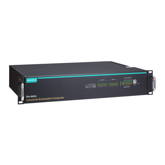
Page 7: Appearance
DA-682A-DPP Hardware Introduction Optional Expansion Modules: • DA-SP08-I-EMC4-DB: 8-port RS-232/422/485 serial module with a digitally isolated DB9 connector; suitable for EMC Level 4 environments • DA-SP08-I-EMC4-TB: 8-port RS-232/422/485 serial module with a digitally isolated terminal block connector; suitable for EMC Level 4 environments •... -
Page 8: Dimensions
DA-682A-DPP Hardware Introduction Dimensions Features The DA-682A-DPP computer has the following features: • IEC 61850-3, IEEE 1613, and IEC 60255 compliant for power substation automation systems • 3rd generation Intel core processors (Ivy Bridge) • Built-in DDR3 SDRAM and industrial DOM •... -
Page 9: Hardware Block Diagram
DA-682A-DPP Hardware Introduction Hardware Block Diagram DA-682A-DPP Basic System Hardware Specifications Basic Systems Computer CPU: 3nd generation Intel core processors (Ivy Bridge) • Intel Celeron 1047UE, 1.4 GHz dual-core processor • Intel Core i3-3217UE, 1.6 GHz dual-core processor • Intel Core i7-3517UE, 1.7 GHz dual-core processor... - Page 10 DA-682A-DPP Hardware Introduction Display Graphics Controller: Intel® HD Graphics (Integrated) Display Interface: 1 VGA output (DB15 female connector) Resolution: CRT display mode with pixel resolution up to 2048 x 1536 at 75 Hz Ethernet Interface LAN: Auto-sensing 10/100/1000 Mbps ports x 6 Magnetic Isolation Protection: 1.5 kV built-in...
-
Page 11: Expansion Modules
DA-682A-DPP Hardware Introduction Expansion Modules Software-Selectable Serial Ports DA-SP08-I-DB DA-SP08-DB DA-SP08-I-TB DA-SP38-I-TB Serial Interface Number of Ports RS-232/422/485 x 8 RS-422/485 x 8 Serial Standards RS-232/422/485, software-selectable RS-422/485 Connector DB9 male DB9 male 5-pin terminal block Protection 15 kV ESD and 2... -
Page 12: Hardware Installation
The DA-682A-DPP embedded computers come with a reliable and stable hardware platform that lets you devote the bulk of your time to application development. This chapter describes hardware installation and connector interfaces of the DA-682A-DPP embedded computers. -
Page 13: Placement Options
Desk Place your DA-682A-DPP on a clean, flat desk. For better ventilation, leave some space between the DA-682A-DPP and other equipment. Do not place equipment or objects on top of the DA-682A-DPP, as this might damage the computer’s internal components. - Page 14 Use 4 FMSM5X10 screws (2 on each bracket) to attach the handles to the brackets. Step 3: Install the brackets Use 6 FMSM4X6 screws to attach a bracket to one side of the DA-682A-DPP. Repeat this procedure on the other side. Step 4: Installing the DA-682A-DPP on a rack.
-
Page 15: Wiring Requirements
DA-682A-DPP Hardware Hardware Installation Use two screws on the left side and two screws on the right side. Check to make sure that the four screws are firmly attached to the rack. screws screws Wiring Requirements The following common safety precautions should be observed before installing any electronic device: •... -
Page 16: Connecting The Power
DA-682A-DPP Hardware Hardware Installation Connecting the Power After you have connected the power cords to the power input unit, the system will automatically boot up. Depending on the operating system, the boot up process can take about 30 to 60 seconds. -
Page 17: Reset Button
DA-682A-DPP Hardware Hardware Installation DC Terminal AC Terminal Reset Button Pressing the Reset button initiates a hardware warm reboot. The button plays the same role as a desktop PC’s reset button. After you press the reset button, the system will reboot automatically. During normal use, you should NOT use the Reset Button. -
Page 18: Connecting To A Display
No operation Connecting to a Display The DA-682A-DPP embedded computer comes with a D-Sub 15-pin female connector to connect to a VGA monitor. Turn off the power source to the computer before you connect or disconnect the monitor cable. Pin No. -
Page 19: Connecting Usb Devices
Connecting USB Devices The DA-682A-DPP embedded computer has four USB 2.0 ports, with two ports on the front panel and the other two on the rear panel. All of the ports are UHCI, Rev 2.0 compliant and support Plug & Play and hot swapping. -
Page 20: Upgrading The Memory Module
The W7E models use DHCP for IP address assignment. Upgrading the Memory Module The DA-682A-DPP embedded computer supports one DDR3 1333/1066 SODIMM module with up to 8 GB capacity. The computer is shipped with one DDR3 SDRAM memory module installed. To replace the SDRAM memory module, follow these instructions: 1. -
Page 21: Installing A Compactflash Card
5. When finished, replace the upper cover of the computer, replace the screws, and fasten the screws to secure the cover. Installing a CompactFlash Card The DA-682A-DPP embedded computer comes with a CompactFlash socket. To insert a CompactFlash card, follow these instructions. 1. Disconnect the DA-682A-DPP from its power source. -
Page 22: Installing A Disk On Module (Dom)
Installing a Disk on Module (DOM) The DA-682A-DPP stores its operating system on a disk-on-module (DOM) that is pre-installed on the computer. You can also install your own DOM as per the following instructions: 1. Disconnect the DA-682A-DPP from its power source. -
Page 23: Installing Sata Hard Disks
Hardware Installation Installing SATA Hard Disks The DA-682A-DPP computer comes with two SATA hard disk installation kits. You can install up to two SATA HDD/SSDs on the computer. The installation steps are as given below: The SATA hard disk installation package contains one SATA power cable, one SATA data cable, one hard drive bracket for a single drive, four bracket screws, and four hard disk screws. - Page 24 DA-682A-DPP Hardware Hardware Installation Step 3: Fasten the hard drive to the bracket using the HDD screws as shown below: Single Disk Bracket Step 4: Take off the upper cover of the computer, and find the locations of the HDD bracket and the SATA Cable/Power Cable.
- Page 25 DA-682A-DPP Hardware Hardware Installation Step 6: Place the hard disk bracket (with the hard disk) face-down on the fixed spacers and secure the bracket using spacer screws as shown below: Step 7: Install the Power Translation Board firmly on the spacers and tighten the 3 bracket screws.
-
Page 26: Installing And Removing Expansion Modules
Installing and Removing Expansion Modules The DA-682A-DPP embedded computer has two slots for DA expansion modules. There is no designated primary or secondary slot; modules may be installed in either slot A or slot B. To install or remove expansion modules, follow these instructions: 1. -
Page 27: Sp08-I-Db/Da-Sp08-Db/Da-Sp08-I-Emc4-Db Serial Expansion Modules
DA-682A-DPP Hardware Hardware Installation DA-SP08-I-DB/DA-SP08-DB/DA-SP08-I-EMC4- DB Serial Expansion Modules The DA-SP08-I-DB, DA-SP08-I-EMC4-DB, and DA-SP08-DB serial expansion modules have 8 software-selectable serial ports with DB9 connectors. The DA-SP08-I-DB and DA-SP08-I-EMC4-DB support 2 kV isolation protection for all signals. In addition, the DA-SP08-I-EMC4-DB is able to withstand EMC level 4 interference. -
Page 28: Da-Irigb-4Dio-Pci104-Emc4 Module
DA-682A-DPP Hardware Hardware Installation DA-IRIGB-4DIO-PCI104-EMC4 Module The DA-682A-DPP models are provided with 1 PCI-104 socket for installing the optional expansion module, DA-IRIGB-4DIO-PCI104-EMC4 for the time-synchronization application. Model Description DA-IRIGB-4DIO-PCI104-EMC4 Time synchronization expansion module, 1 IRIG-B signal input port, 3 digital inputs, 4 digital outputs... -
Page 29: Connecting A Da-Irigb-B-S Module
DA-682A-DPP Hardware Hardware Installation Connecting a DA-IRIGB-B-S Module ATTENTION To prevent damage to your system or the main board, make sure that you turn off the embedded computer before installing the DA-IRIGB-B-S Series module. 1. Turn the embedded computer off. - Page 30 DA-682A-DPP Hardware Hardware Installation c. Install the DB9 connectors on the rear panel of the embedded computer and replace the computer cover. 7. Turn on the embedded computer. The BIOS will automatically set the IRQ and I/O address. 2-19...
-
Page 31: Bios Setup
BIOS Setup This chapter describes the BIOS settings of the DA-682A-DPP computer. The BIOS is a set of input/output control routines for peripherals. The BIOS is used to initialize system peripherals before the operating system is loaded. The BIOS setup allows the user to modify the system configurations of these peripherals’ basic input/output. -
Page 32: Entering The Bios Setup
DA-682A-DPP Hardware BIOS Setup Entering the BIOS Setup To enter the BIOS setup utility, press the “F2” key while the system is booting up. The main BIOS Setup screen is displayed. The following four options are available: Continue: Continue to boot up... -
Page 33: Main Information
DA-682A-DPP Hardware BIOS Setup The following BIOS configuration screen will be shown when you enter SCU option: NOTE The information displayed for Processor Type may vary depending on the computer model that you have purchased. Main Information The Main page indicates the system information, such as model name, BIOS version, and CPU type. You can view the basic system hardware information on this page. -
Page 34: Boot Configuration
DA-682A-DPP Hardware BIOS Setup Boot Configuration This feature allows you to configure a default setting for the keys on the number pad of the computer keyboard. Turning the NumLock on allows you to use the number keys to type out numbers and turning the Num Lock off enables the key's other functions, such as using the keypad as an arrow pad. -
Page 35: Video Configuration
DA-682A-DPP Hardware BIOS Setup Serial ATA Port 0 to 3 This setting allows the user to display information about the installed drives. AHCI SALP Please note that the AHCI SALP option is only available when you select the AHCI mode. This option allows you to enable aggressive link power management (SALP) in AHCI. -
Page 36: Chipset Configuration
DA-682A-DPP Hardware BIOS Setup IGD—DVMT Pre-Allocated Allows you to configure pre-allocated memory capacity for the IGD. Pre-allocated graphics memory is invisible to the operating system. Options: 64 MB (default), 32 MB, 96 MB, 128 MB, 256 MB, 512 MB DVMT is a BIOS solution where the optimum amount of memory is dynamically allocated and de-allocated as needed for balanced graphics and system performance, through Intel®... -
Page 37: Hardware Monitor
DA-682A-DPP Hardware BIOS Setup Hardware Monitor This feature allows you to view hardware statistics like CPU and system temperature, voltage levels, and other chipset information. Please note that the voltage values will vary depending on the different models, and there will be 5% tolerance for the temperature values. -
Page 38: Set Supervisor Password
Turbo Mode Allows you to enable/disable the Intel CPU Turbo Boost technology on your computer. Options: Enabled (default), Disable. Please note that this option is only available on the DA-682A-DPP-C7, DA-682A-DPP-C7-LX, and DA-682A-DPP-C7-W7E models. Auto Wake on S5 This feature allows you to configure auto wake up from S5 status. S5 stands for Soft Off, where the PSU remains engaged but power to all other parts of the system is cut off. -
Page 39: Wake On Lan
DA-682A-DPP Hardware BIOS Setup Options: Disabled (default); By Every Day (user specifies a regular daily time when the computer will power up); By Day of Month (user specifies a regular day each month when the computer will power up) Wake on LAN This feature is used to configure a wake on the system by a LAN device from a remote host. -
Page 40: Usb Boot
DA-682A-DPP Hardware BIOS Setup USB Boot Allows you to enable/disable USB boot function. Options: Enabled (default), Disabled EFI Device First Allows you to determine EFI device first or legacy device first. If enabled, EFI device will be the first; if disabled, legacy device will be the first. -
Page 41: Exit Saving Changes
DA-682A-DPP Hardware BIOS Setup Exit Saving Changes Allows you to exit the BIOS environment and save the values you have just configured. Options: Yes (default), No Save Change Without Exit Allows you to save changes without exiting the BIOS environment. - Page 42 2. Copy the file to the Bootable USB Disk. Step 3: Run the upgrade program on the DA-682A-DPP Computer 1. Reboot the computer, press F12 while booting up to enter the Boot Manager 2. Select USB Disk as the first boot source. Press Enter to continue.
- Page 43 DA-682A-DPP Hardware BIOS Setup 3. When the boot up process is complete, the DOS screen is displayed. Go to the directory where the upgrade cd DA682A file is located. For example, if the upgrade file is stored in the DA682A folder, type C:\cd DA682A 4.
- Page 44 DA-682A-DPP Hardware BIOS Setup ATTENTION Do NOT switch off the power supply during the BIOS upgrade, since doing so may cause the system to crash. 3-14...
- Page 45 Safety Installation Instructions A. RTC Battery Warning CAUTION: There is a risk of explosion if battery is replaced by an incorrect type. Dispose of used batteries according to the instructions. B. Fuse Warning CAUTION: For continued protection against fire, replace only with same type and rating of fuse. C.
Need help?
Do you have a question about the DA-682A-DPP and is the answer not in the manual?
Questions and answers