
Related Manuals for Moxa Technologies DA-683 Series


Summary of Contents for Moxa Technologies DA-683 Series
- Page 1 DA-683 Series Embedded Computer User’s Manual First Edition, January 2011 www.moxa.com/product © 2011 Moxa Inc. All rights reserved. Reproduction without permission is prohibited.
-
Page 2: Copyright Notice
Information in this document is subject to change without notice and does not represent a commitment on the part of Moxa. Moxa provides this document as is, without warranty of any kind, either expressed or implied, including, but not limited to, its particular purpose. Moxa reserves the right to make improvements and/or changes to this manual, or to the products and/or the programs described in this manual, at any time. -
Page 3: Table Of Contents
Table of Contents Introduction............................1-1 Overview ............................1-2 Model Descriptions and Package Checklist....................1-2 Appearance............................1-3 Features ............................1-4 Hardware Block Diagram ........................1-4 Hardware Specifications ........................1-5 Non-standard Baudrates ........................1-6 Hardware Installation ........................2-1 ... -
Page 4: Introduction
Introduction Thank you for purchasing the Moxa DA-683 series x86-based industrial ready-to-run embedded computer. This manual introduces the hardware installation, connector interfaces and BIOS setup of the DA-683. For software configuration and management, please refer to the user’s manual for your operating system. -
Page 5: Overview
8-port 10/100 Mbps switch module, and a universal PCI expansion module. Wide temperature models of the DA-683 Series that operate reliably in a -40 to 70°C operating temperature range are also available, offering an optimal solution for applications subjected to harsh environments. -
Page 6: Appearance
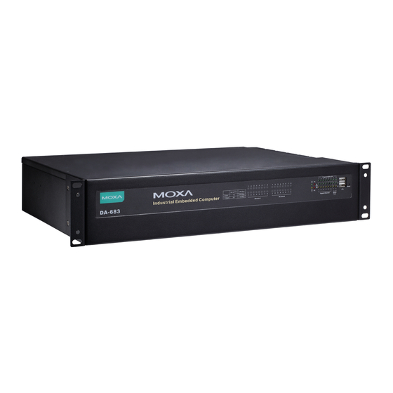
DA-683 Series Introduction Appearance Front View (Programmable x 8) Module Slot B Module Slot A (Serial, Tx x 2, Rx x 2) LED x 16 LED x 16 (Gigabit LAN x 12) (Serial/LAN) (Serial/LAN) Reset Button USB 2.0 19-inch Rackmount Ear... -
Page 7: Features
DA-683 Series Introduction Features The DA-683 computer has the following features: • IEC 61850-3 certified for power substation automation systems (DPP-T models only) • Intel Dual Core Atom D510 1.66 GHz processor • DDR2 SODIMM socket, supporting DDR2 667 up to 2 GB (max.) •... -
Page 8: Hardware Specifications
DA-683 Series Introduction Hardware Specifications Computer CPU: Intel Dual Core Atom D510 1.66 GHz processor OS (pre-installed): Linux or Windows Embedded Standard 2009 System Chipset: Intel Pineview-D + ICH8M BIOS: 16 Mbit Flash BIOS, PCI Plug & Play, ACPI function support FSB: 667 MHz System Memory: 1 x 200-pin DDR2 SODIMM socket supporting DDR2 667;... -
Page 9: Non-Standard Baudrates
Details: See www.moxa.com/warranty Non-standard Baudrates Moxa’s UART ASIC, supports most non-standard baudrates in the range 50 bps to 921.6 Kbps. In fact, supported baudrates are much denser towards the lower values. For example, no baudrates are supported between the integers 5320 and 5323, but 49 baudrates are supported between the integers 387 and 388. Of course this is the way it should be, since serial devices that require using non-standard baudrates generally use slower baudrates. - Page 10 WARNING Communication between a serial device and a Moxa UART port may not work correctly if the serial device uses a baudrate that it not within the correct tolerance of a baudrate calculated from either formula A or formula B.
-
Page 11: Hardware Installation
Hardware Installation The DA-683 Series of embedded computers are compact and rugged, making them suitable for industrial applications. The LED indicators allow users to monitor performance and identify trouble spots quickly, and multiple ports are provided for connecting a variety of different devices. The DA-683 embedded computers come with a reliable and stable hardware platform that lets you devote the bulk of your time to application development. -
Page 12: Placement Options
DA-683 Series Hardware Installation Placement Options Desktop Place your DA-683 on a clean, flat, well-ventilated desktop. For better ventilation, leave some space between the DA-683 and other equipment. Do not place equipment or objects on top of the DA-683, as this might damage the computer’s internal components. - Page 13 DA-683 Series Hardware Installation Step 2: Installing rackmount hanger to the support. Use 2 FMSM5X10 screws to attach the rackmount hanger to the ear. Repeat this procedure for the additional support and hanger. Step 3: Installing the rackmount ears to the DA-683.
-
Page 14: Wiring Requirements
DA-683 Series Hardware Installation As a final check, make sure that the four screws are firmly attached to the rack. Wiring Requirements The following common safety precautions should be observed before installing any electronic device: • Use separate paths to route wiring for power and devices. If power wiring and device wiring paths must cross, make sure the wires are perpendicular at the intersection point. -
Page 15: Connecting The Power
DA-683 Series Hardware Installation Connecting the Power The DA-683 offers both single power and dual power inputs. Use a screwdriver to remove the screws. Connect the power cord to the screws and then attach the screws to the unit. For single models (SP), use Power 1 only;... -
Page 16: Power Input Wiring Description
DA-683 Series Hardware Installation For DPP-T Models PWR 1 PWR 2 Power 2 Power 1 Surge Ground Chassis Ground Protection Earth Chassis Ground Surge Ground AC Terminal Protection Earth (Green & Yellow) Line (Black) Bond Earth (Green) Neutral (White) Power Input Wiring Description Read the following section for a detailed power input wiring description. - Page 17 DA-683 Series Hardware Installation Terminal Number Description Note PWR1 Line + is connected, or to the Line terminal PWR1 Line for the AC power source. PWR1 Neutral – is connected to the Neutral PWR1 Neutral terminal for the AC power source.
-
Page 18: Hipot (Dielectric Strength) Testing
DA-683 Series Hardware Installation HIPOT (Dielectric Strength) Testing Before performing the HIPOT test, you MUST have the jumpers removed and the braided ground cable disconnected. This is required to prevent the transient/surge suppression circuitry, which is connected to Surge Ground from being activated during the HIPOT test. -
Page 19: Connecting To A Display
DA-683 Series Hardware Installation LED Name Color LED Description Power Green Power is on No power input or power error Storage Yellow / Data is being written to or to read from the storage unit Blinking Storage unit is idle... -
Page 20: Connecting A Ps/2 Keyboard And Mouse
DA-683 Series Hardware Installation Connecting a PS/2 Keyboard and Mouse Your DA-683 embedded computer comes with a PS/2 mini-DIN connector to connect to a PS/2 keyboard and PS/2 mouse by using a Y-type cable. This 6-pin mini-DIN connector has the pin assignments shown below. -
Page 21: Connecting Usb Devices
DA-683 Series Hardware Installation Connecting USB Devices The DA-683 embedded computer has four USB 2.0 ports: two are on the front panel, and two are on the rear panel. All of the ports are UHCI, Rev 2.0 compliant and support Plug & Play and hot swapping. These ports can be used to connect USB devices, such as a keyboard, mouse, USB flash disk, and USB CD-ROM. -
Page 22: Connecting Digital Input/Output Channels
DA-683 Series Hardware Installation The default IP addresses and netmasks of the Gigabit LAN ports are as follows: Default IP Address Netmask LAN 1 192.168.3.127 255.255.255.0 LAN 2 192.168.4.127 255.255.255.0 LAN 3 192.168.5.127 255.255.255.0 LAN 4 192.168.6.127 255.255.255.0 LAN 5 192.168.7.127... - Page 23 DA-683 Series Hardware Installation 1. Disconnect the DA-683 from the power source. 2. The DA-683’s memory module is located inside the DA-683. Use a screwdriver to remove the screws on the top cover of the DA-683. Screws Screws 3. After removing the cover, you will see the DDR2 SDRAM module.
-
Page 24: Installing A Compactflash Card
DA-683 Series Hardware Installation 5. Gently insert the new memory into the module. Make sure the direction is correct. 6. Push the memory all the way down to complete installation. Installing a CompactFlash Card The DA-683 embedded computer comes with a CompactFlash socket. To insert a CompactFlash card, follow these instructions. -
Page 25: Installing A Sata Hard Disk
DA-683 Series Hardware Installation 3. Insert the CompactFlash card into the socket. Push downwards to make sure that the card is firmly inserted. ATTENTION Make sure you insert the card in the right direction. The card cannot be inserted if you insert the card in the wrong direction. - Page 26 DA-683 Series Hardware Installation Please note that for SP models, the DA-683 allows users to install two hard disk drives inside the computer. Users can install the hard disks at the first and second hard disk bays. For DPP-T models, users can only install one hard disk at the first bay, as the second installation bay has been occupied by the second power input.
-
Page 27: Installing A Pci 104 Board
DA-683 Series Hardware Installation 10. Connect the power cable and SATA cable to the connectors on the computer. SATA Connectors Power Connector ATTENTION The SATA hard disk cable and SATA power cable are not included in the basic shipment of the DA-683 embedded computer. -
Page 28: Upgrading A Dom
DA-683 Series Hardware Installation Upgrading a DOM The DA-683 comes with a IDE-based DOM in which the operating system has been installed. To upgrade this DOM, follow these step. 1. Disconnect the DA-683 from its power source. 2. Open the top cover of the DA-683. Refer to the following figure for the specific location for the DOM installation. - Page 29 DA-683 Series Hardware Installation 2. Unscrew expansion module A or module B on the rear panel. 3. Carefully insert or remove the expansion module by pushing or pulling on the two screws at the same time. By pushing or pulling on the two screws evenly, you can ensure that the board is inserted or removed without being damaged.
-
Page 30: Bios Setup
BIOS Setup This chapter describes the BIOS settings of the DA-683 Computer. The BIOS is a set of input/output control routines for peripherals. The BIOS is used to initialize basic peripherals and helps boot the operating system before the operating system is loaded. The BIOS setup allows the user to modify the system configurations of these basic input/output peripherals. -
Page 31: Entering The Bios Setup Utility
DA-683 Series BIOS Setup Entering the BIOS Setup Utility To enter the BIOS setup utility, press the “F2” key while the system is booting up. The main BIOS Setup screen will appear. A basic description of each function key is listed at the bottom of the screen. Refer to these descriptions to learn how to scroll about the screen, how to select by pressing “Enter,”... -
Page 32: Modifying The Bios Main Settings
DA-683 Series BIOS Setup Modifying the BIOS Main Settings Advanced Settings The “Advanced Features” screen will appear when choosing the “Advanced” item from the main menu. Boot Configuration This item allows users to configure the default value of Numlock. Option: On (default), Off. -
Page 33: Peripheral Configuration
DA-683 Series BIOS Setup Peripheral Configuration This item allows you to configure the parallel port and audio device. Serial Port A This item allows you to configure the parallel port. Options: 378/IRQ7 (default), Disabled Serial Port B This item allows you to configure the parallel port. -
Page 34: Ide Configuration
DA-683 Series BIOS Setup IDE Configuration This item allows you to configure the hard disk controllers. HDC Configure As This item allows you to configure the hard disk type. Options: AHCI (default), PATA Only, SATA Only, IDE Non-Combined Channel Master 1 to 3 This setting displays the storage devices installed on the Master mode in the computer. -
Page 35: Video Configuration
DA-683 Series BIOS Setup Video Configuration This item allows you to configure the video settings. VGA card This item allows you to select the onboard VGA chipset or the external VGA card installed in the PCI slot.. Options: IGD (default), PCI IGD –... -
Page 36: Usb Configuration
DA-683 Series BIOS Setup USB Configuration This item allows you to configure the USB settings. USB Legacy This item allows you to configure the USB devices that can be accessed during boot-up and in DOS. Options: Enabled (default), Disabled ACPI Table/Features Control... -
Page 37: Hardware Monitor
DA-683 Series BIOS Setup FACP – RTC S4 Wakeup This item allows you to enable the operating system through RTC when in sleep mode.. Options: Enabled (default), Disabled HPET – HPET Support This item allows you to enable/disable the HPET (High Precision Event Timer) function. -
Page 38: Security Settings
DA-683 Series BIOS Setup Security Settings The section allows users to configure security settings with supervisor password and user password. Set Supervisor Password This item allows you set the supervisor password. Select and then enter the password, and then confirm the password again. -
Page 39: Power Settings
DA-683 Series BIOS Setup Power Settings The section allows users to configure power settings. Advanced CPU Control ACPI S3 This item allows you to enable/disable Processor Performance States (P-States) function. Options: Disabled (default), Enabled PWRON after PWR-Fail (Power on after Power Fail) This item allows you to configure the power on after power fail function. -
Page 40: Boot Settings
DA-683 Series BIOS Setup HT Support This item allows you to configure the Hyper-Threading (HT) function. Options: Auto (default), Disabled Use XD Capability This item allows you to enable/disable the Intel XD function.. Options: Enable (default), Disabled Boot Settings The section allows users to configure boot settings. -
Page 41: Exit Settings
DA-683 Series BIOS Setup This item displays the boot selection for the UEFI boot function. Legacy Normal Boot Menu This item allows you to configure the boot menu. Options: Normal (default), Advance Boot Type Order This item allows you to select the boot order. Use F5/F6 to change values. -
Page 42: Upgrading The Bios
This section describes how to upgrade the BIOS. However, please note that upgrading the BIOS involves high risk of damage to your computer. We strongly recommend that you contact Moxa’s TS staff for assistance and obtain all necessary tools and files before attempting to upgrade. - Page 43 Step 2: Prepare the Upgrade File. You must use the BIOS upgrade installation file to upgrade the BIOS. You can send your request to Moxa's technical support team at support@moxa.com to get an updated version of the BIOS. 1. Get the BIOS upgrade installation file. The file name should have following format: 683xxSxx.exe (xx refers to version numbers) 2.
- Page 44 DA-683 Series BIOS Setup Boot Manager Boot Option Menu MOXA SSD Generic USB Flash Disk ↑ and ↓ to change option, ENTER to select an optin, ESC to exit 3. Once the computer boots, a DOS screen will appear. Go to the directory where the upgrade file is located.
- Page 45 DA-683 Series BIOS Setup ATTENTION Do NOT switch off the power supply during the BIOS upgrade, since doing so may cause the system to crash. 3-16...
-
Page 46: Safety Installation Instructions
Safety Installation Instructions A. RTC Battery Warning CAUTION: There is a risk of explosion if battery is replaced by an incorrect type. Dispose of used batteries according to the instructions. B. Fuse Warning CAUTION: For continued protection against fire, replace only with same type and rating of fuse. C. -
Page 47: Regulatory Statement Approval
Regulatory Statement Approval This device complies with part 15 of the FCC Rules. Operation is subject to the following two conditions: (1) This device may not cause harmful interference, and (2) this device must accept any interference received, including interference that may cause unde sired operation.
Need help?
Do you have a question about the DA-683 Series and is the answer not in the manual?
Questions and answers