
Related Manuals for Moxa Technologies DA-820-C8-SP-HV


Summary of Contents for Moxa Technologies DA-820-C8-SP-HV
- Page 1 DA-820 Series Embedded Computer User’s Manual Edition 2.1, August 2019 www.moxa.com/product © 2019 Moxa Inc. All rights reserved.
- Page 2 DA-820 Series Embedded Computer User’s Manual The software described in this manual is furnished under a license agreement and may be used only in accordance with the terms of that agreement. Copyright Notice © 2019 Moxa Inc. All rights reserved. Trademarks The MOXA logo is a registered trademark of Moxa Inc.
-
Page 3: Table Of Contents
Table of Contents Introduction ............................1-1 Overview ............................1-2 Model Descriptions and Package Checklist ....................1-2 Appearance ............................1-3 Dimensions ............................1-5 Features ............................1-5 Hardware Block Diagram ........................1-6 DA-820 Basic System ........................1-6 Hardware Specifications ........................1-6 Hardware Installation ........................2-1 Wiring Requirements ........................... -
Page 4: Introduction
Introduction Thank you for purchasing a Moxa DA-820 industrial computer, a multi-functional embedded computer designed especially for IEC 61850-3 substation automation systems. This manual covers hardware installation, connector interfaces, and BIOS setup of the DA-820. For software configuration and management, please refer to the user’s manual for your operating system. The following topics are covered in this chapter: ... -
Page 5: Overview
DA-820-C8-DP-HV: Rackmount computer with Intel i7-3612QE, quad-core 2.1 GHz CPU, 100 to 240 V AC/DC power supplies x 2, -40 to 60°C operating temperature (without CFast/RAM/OS) • DA-820-C8-SP-HV: Rackmount computer with Intel i7-3612QE, quad-core 2.1 GHz CPU, 100 to 240 V AC/DC power supply, -40 to 60°C operating temperature (without CFast/RAM/OS) •... -
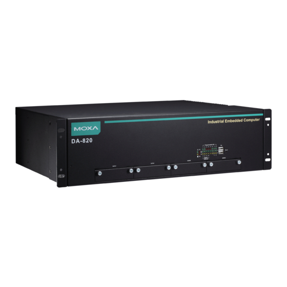
Page 6: Appearance
DA-820 Series Introduction • DA-820-C3-SP-HV-T: Rackmount computer with Intel i3-3217UE, dual-core 1.6.5 GHz, 100 to 240 V AC/DC, -40 to 75°C operating temperature (without CFast/RAM/OS) • DA-820-C1-DP-LV-T: Rackmount computer with Intel Celeron 1047UE, dual-core 1.4 GHz, 24 to 110 VDC x 2, -40 to 75°C operating temperature (without CFast/RAM/OS) •... - Page 7 DA-820 Series Introduction Rear View *The power input supports two types of power supply (refer to the section "Connecting the Power" in Chapter 2 for details): HV: 100 to 240 V AC/DC LV: 24 to 110 VDC...
-
Page 8: Dimensions
DA-820 Series Introduction Dimensions Unit = mm (inch) Features The DA-820 computer has the following features: • Intel® Core™ Celeron, i3, and i7 CPU with QM77 chipset • 2 x 204-pin SO-DIMM DDR3 sockets, supporting un-buffered ECC DDR3 memory at 1333 and 1600 MT/s, 16 GB max. -
Page 9: Hardware Block Diagram
DA-820 Series Introduction Hardware Block Diagram DA-820 Basic System Hardware Specifications NOTE The latest specifications for Moxa’s products can be found at https://www.moxa.com. -
Page 10: Hardware Installation
Hardware Installation The DA-820 embedded computers are compact and rugged, making them suitable for industrial applications. The LED indicators allow users to monitor performance and identify trouble spots quickly, and multiple ports are provided for connecting a variety of different devices. The DA-820 embedded computers come with a reliable and stable hardware platform that lets you devote the bulk of your time to application development. -
Page 11: Wiring Requirements
DA-820 Series Hardware Installation Wiring Requirements The following common safety precautions should be observed before installing any electronic device: • Power wires and communication/signal wires should be routed through separate paths. If power and communication/signal wires must cross paths, make sure the wires are perpendicular at the intersection point. -
Page 12: Wiring The Power Inputs
DA-820 Series Hardware Installation Wiring the Power Inputs Refer to the following diagrams and table for a detailed description of the power input wiring. The terminal numbers referred to in the table are shown in the leftmost diagram below. Terminal Number Description Note PWR1 Line (+) is connected to the Line terminal for the AC... - Page 13 3. Surge Ground is connected to the Chassis Ground via a braided cable or other appropriate grounding wire. Surge Ground is used as the ground conductor for all surge and transient suppression circuitry internal to the protection board. 4. Chassis Ground should be connected to the AC Ground terminal. Alternating Current (AC), Single Power Models: DA-820-C8-SP-HV, DA-820-C7-SP-HV-T...
- Page 14 DA-820 Series Hardware Installation Alternating Current (AC), Dual Power Models: DA-820-C8-DP-HV, DA-820-C7-DP-HV-T...
- Page 15 DA-820 Series Hardware Installation Direct Current (DC), Single Power Models: DA-820-C8-SP-HV, DA-820-C8-SP-LV, DA-820-C7-SP-HV-T, DA-820-C7-SP-LV-T...
- Page 16 DA-820 Series Hardware Installation Direct Current (DC), Dual Power Models: DA-820-C8-DP-HV, DA-820-C8-DP-LV, DA-820-C7-DP-HV-T, DA-820-C7-DP-LV-T...
- Page 17 DA-820 Series Hardware Installation ATTENTION 1. Equipment must be installed according to the applicable country wiring codes. 2. Surge Ground MUST be disconnected from the Chassis Ground during HIPOT (dielectric strength) testing. 3. All line-to-ground transient energy is shunted to the Surge Ground terminal. In cases where users require the inputs to be isolated from the ground, remove the ground braid between Surge and Chassis Ground.
-
Page 18: Hipot (Dielectric Strength) Testing
DA-820 Series Hardware Installation HIPOT (Dielectric Strength) Testing Before performing the HIPOT test, you MUST remove the jumpers and disconnect the braided ground cable. Doing so can prevent the transient/surge suppression circuitry (which is connected to Surge Ground) from being activated during the HIPOT test. When finished, press the Power Switch button to start the system. -
Page 19: Reset Button
DA-820 Series Hardware Installation Reset Button Pressing the Reset button initiates a hardware warm reboot. The button plays the same role as a desktop PC’s reset button. After pressing the reset button, the system will reboot automatically. During normal use, you should NOT use the Reset Button. -
Page 20: Connecting To A Display
DA-820 Series Hardware Installation Connecting to a Display Your DA-820 embedded computer comes with two D-Sub 15-pin female connectors to connect to the VGA monitor. Be sure to disconnect the power before you connect or disconnect the monitor cable. Pin No. Signal Definition GREEN BLUE... -
Page 21: Connecting Usb Devices
DA-820 Series Hardware Installation Connecting USB Devices The DA-820 embedded computer has six USB 2.0 ports, with two ports on the front panel and the other four on the rear panel. All of the ports are UHCI, Rev 2.0 compliant and support Plug & Play and hot swapping. These ports can be used to connect USB devices, such as a keyboard, mouse, USB flash disk, and USB CD-ROM. - Page 22 DA-820 Series Hardware Installation 2. Attach the USB Dongle bracket to the tray. 3. Plug your USB dongle into the USB port of the dongle bracket. Mini-sized dongle Normal sized dongle 4. Disconnect the power source to your DA-820. 5. Open the top cover of the DA-820. 6.
- Page 23 DA-820 Series Hardware Installation 7. Install the USB Tray (with the USB dongle) and tighten the screws to secure the USB dongle tray as shown below: The USB Dongle Kit should be installed as close to the memory socket as possible as shown in the following image: 2-14...
-
Page 24: Gigabit Lan Ports
DA-820 Series Hardware Installation 8. Connect the USB cable to the onboard USB connector that is closest to the memory socket. Gigabit LAN Ports The DA-820 Basic System has 4 Gigabit LAN ports. When a LAN cable is properly connected, the LEDs on the RJ45 connectors will glow to indicate a proper connection. -
Page 25: Upgrading The Memory Module
DA-820 Series Hardware Installation Upgrading the Memory Module The DA-820 embedded computer supports 2 ECC registered DDR3 1333/1600 SODIMM modules, for up to 16 GB of memory (2 slots, each with 8 GB). To upgrade the SDRAM memory module, follow these instructions: 1. -
Page 26: Installing A Cfast Card
DA-820 Series Hardware Installation Installing a CFast Card The DA-820 embedded computer comes with a CFast socket. To insert a CFast card, follow these instructions. 1. Disconnect the DA-820 from its power source. 2. Unfasten the screws on the back of the computer, and then take off the upper cover. 3. -
Page 27: Installing Sata Hard Disks
DA-820 Series Hardware Installation Installing SATA Hard Disks The DA-820 comes with four SATA slots that allow users to install 2.5” SATA HDD/SSD in the computer. Follow these steps to install a SATA disk. Step 1: Loosen screws from each of the four SATA slots (SATA1 is used to illustrate). Step 2: Remove the SATA HDD Tray from the computer itself. - Page 28 DA-820 Series Hardware Installation Step 4: Insert the SATA Tray into original SATA slot and fasten the screws. 2-19...
-
Page 29: Bios Setup
BIOS Setup This chapter describes the BIOS settings of the DA-820 computer. The BIOS is a set of input/output control routines for peripherals, and is used to initialize system peripherals before the operating system is loaded. The BIOS setup allows the user to modify the system configurations of these peripherals’ basic input/output. The following topics are covered in this chapter: ... -
Page 30: Entering The Bios Setup
DA-820 Series BIOS Setup Entering the BIOS Setup To enter the BIOS setup utility, press the “F2” key while the system is booting up. The main BIOS Setup screen will appear. Five options will be available: • Continue: Continue to boot up •... -
Page 31: Main Page
DA-820 Series BIOS Setup The BIOS configuration screen will be shown when you enter the SCU option, as shown in the following figure. Note that the Processor Type information for will vary depending on which model you purchased. Main Page The Main page displays basic system hardware information, such as model name, BIOS version, and CPU type. -
Page 32: Advanced Settings
DA-820 Series BIOS Setup Advanced Settings Select the “Advanced” option in the main menu to open the “Advanced Features” screen. NOTE The Active Management Technology is only supported in DA-820-C7 and DA-820-C8 models. Boot Configuration This item allows users to configure the default value of Numlock. Options: On (default), Off. -
Page 33: Hdc Configuration
DA-820 Series BIOS Setup HDC Configuration The host drive controller can be configured for IDE (legacy default) or AHCI mode. When the legacy IDE mode is selected, the following screen will appear. Serial ATA Port <0 to 4> This setting allows the user to display information about the installed drives. - Page 34 DA-820 Series BIOS Setup AHCI SALP AHCI SALP will only appear when AHCI or RAID mode is selected. This item allows you to enable aggressive link power management (SALP) in AHCI/RAID. SALP enables the host bus adapter to conserve power by directly detecting when a SATA drive is no longer processing information and then immediately shifting it into suspended or sleep modes without waiting for software processes to initiate power-down processes.
- Page 35 DA-820 Series BIOS Setup These figures were obtained from Wikipedia. Please refer to http://en.wikipedia.org/wiki/Standard_RAID_levels for details. NOTE Smart Recovery is not supported under RAID mode.
-
Page 36: Video Configuration
DA-820 Series BIOS Setup Video Configuration This item allows you to configure the built-in Internal Graphics Device or external PCI Express Graphics card. Options: IGFX (default), PEG Internal Graphics Device This option allows you to enable/disable the internal graphics device. Options: Enabled (default), Disabled... -
Page 37: Pci Express Graphics
DA-820 Series BIOS Setup IGD—DVMT Pre-Allocated This item allows you to configure pre-allocated memory capacity for the IGD. Pre-allocated graphics memory is invisible to the operating system. Options: 64 MB (default), 32 MB, 96 MB, 128 MB, 256 MB, 512 MB DVMT is a BIOS solution where “the optimum amount of memory is dynamically allocated and de-allocated as needed for balanced graphics and system performance, through Intel®... -
Page 38: Chipset Configuration
DA-820 Series BIOS Setup PCIE Reset Delay When the PCI-E x16 card cannot be detected, try to modify this setting. Options: 100 ms (Default), 50 ms, 200 ms, 300 ms PCIEx16-GEN X Set the PCIEx16 interface speed. The default is auto-detect. You can set a fixed speed for when a card cannot be detected. - Page 39 DA-820 Series BIOS Setup Vt-d (C7 and C8 Models Only This item allows you to enable/disable the Intel® Virtualization Technology For Directed I/O. Options: Enabled (default), Disabled Power ON after Power Failure This item allows you to enable/disable the computer from automatically powering up after a system crash. Options: ON (default), OFF, Last State Rear Panel USB function This item allows you to enable/disable the USB functions on the rear panel in order to restrict USB accessibility...
-
Page 40: Active Management Technology Support
DA-820 Series BIOS Setup Active Management Technology Support This item allows you to configure the Intel ® Active Management Technology and is available only in the C7 and C8 models. Hide Un-Configure ME Confirmation This item allows you to enable/disable hide un-configure ME without password confirmation prompt. Options: Disabled (default), Enabled Un-Configure ME This item allows you to enable/disable hide un-configure ME without password. -
Page 41: Pci Express Configuration
DA-820 Series BIOS Setup PCI Express Configuration This item allows you to configure PCIe slot settings. PCIE x 1 Slot <1 to 3> This item allows you to configure the PCIe speed of each PCIe x1 slot. Options: Auto (default), Gen1, Gen2 3-13... -
Page 42: Hardware Monitor
DA-820 Series BIOS Setup Hardware Monitor This item allows you to view stats such as CPU and system temperature, voltage levels, and other chipset information. The voltage values will vary depending on which model you purchased. There is a 5% tolerance for temperature values. -
Page 43: Smart Recovery Info
DA-820 Series BIOS Setup SMART RECOVERY Info This item allows you to view the status of smart recovery settings. Load SMART RECOVERY Default This item allows you to load the Smart Recovery default value. For details, refer to the Smart Recovery Website: http://www.moxa.com/product/Smart-Recovery.htm Options: Yes (default), No NOTE... -
Page 44: Security Settings
DA-820 Series BIOS Setup Security Settings This section allows users to configure security-related settings with a supervisor password and user password. TPM Status This item allows you view the status of current TPM settings. TPM Operation This item allows you enable/disable the TPM. When an operation is completed, this item will be reset to No Operation. -
Page 45: Tpm Force Clear
DA-820 Series BIOS Setup TPM Force Clear This item allows the user to clear the TPM password. It is used when the user forgets the password. Note that all data protected by TPM will not be accessible. Options: Disabled (default), Enabled Set Supervisor Password This item allows you to set the supervisor password. -
Page 46: Power Settings
DA-820 Series BIOS Setup After the password is reset a pop-up menu is displayed in the security tab. Enable: System will ask input password on post time. Disable: System will ask for the password to go to the setup utility. Config-Only: System will only ask for the password when you select the config (F2) option Power Settings The section allows users to configure power settings. -
Page 47: Turbo Mode (C7 And C8 Models Only)
DA-820 Series BIOS Setup Turbo Mode (C7 and C8 Models Only) This item allows users to determine whether to enable the Intel CPU Turbo Boost technology. Options: Enabled (default), Disabled TXT (C7 and C8 Models Only) This item allows users to enable/disable Intel Trusted Execution Technology (Intel TXT). Options: Disabled (default), Enabled Auto Wake on S5 This item allows you to configure the computer to wake from S5 status. -
Page 48: Boot Settings
DA-820 Series BIOS Setup Boot Settings The section allows users to configure boot settings. NOTE If you do not add any storage, you will not see the Legacy option. Boot Type This item allows you to enable/disable the quick boot function. Options: Dual Boot Type (default), Legacy Boot Type, UEFI Boot Type PXE Boot to LAN This item allows you to enable/disable the PXE boot to LAN function. -
Page 49: Efi Device First
DA-820 Series BIOS Setup EFI Device First This item allows you to determine if the EFI device is activated first, or the legacy device is activated first. If enabled, EFI device will be the first; if disabled, legacy device will be the first. Options: Disabled (default), Enabled Boot Delay Time This item allows you to configure the delay time value for users to input the hot key during POST time. - Page 50 DA-820 Series BIOS Setup Boot Type Order This item allows you to select the boot order. Use +/F5 (move up) or -/F6 (move down) to change values. Options: Hard Disk Drive (default), CD/DVD-ROM Drive, USB, Others Hard Disk Drive/USB Drive This item allows you to view installed devices such as hard disk drives, USB drives, or CD-ROMs.
-
Page 51: Exit Settings
DA-820 Series BIOS Setup Exit Settings The section allows users to exit the BIOS environment. Exit Saving Changes This item allows you to exit the BIOS environment and save the values you have just configured. Options: Yes (default), No Save Change Without Exit This item allows you to save changes without exiting the BIOS environment. -
Page 52: Load Optimal Defaults
DA-820 Series BIOS Setup Load Optimal Defaults This item allows you to revert to the factory default BIOS values. Options: Yes (default), No Load Custom Defaults This item allows you to load custom default values for the BIOS settings. Options: Yes (default), No Save Custom Defaults This item allows you to save the current BIOS values as a “custom default”... - Page 53 DA-820 Series BIOS Setup 1. Select MEBx to enter the AMT configuration. 2. Press <Enter> to start the login procedure. 3-25...
- Page 54 DA-820 Series BIOS Setup 3. Type the default password: admin 4. Type the new password. It must include both upper-case and lower-case characters, numbers, and special symbols. E.g., Admin’12. 5. To enable remote access without a local user present for consent, select User Consent, and then select User Opt-in and change the value to None.
- Page 55 DA-820 Series BIOS Setup 6. Set static IP or DHCP by request. 7. Set Activate Network Access to enable remote access capability. 3-27...
-
Page 56: Use Amt
DA-820 Series BIOS Setup Use AMT You can use any of the available AMT tools to execute the remote management function. The easiest method is using a web browser. 1. Type the IP for your DA-820 that was configured in the AMT configuration with port 16992. The AMT logon screen will appear. -
Page 57: Upgrading The Bios
DA-820 Series BIOS Setup Upgrading the BIOS This section describes how to upgrade the BIOS. However, note that it is easy to permanently damage the computer when upgrading the BIOS. We strongly recommend that you contact Moxa’s technical support staff for assistance in order to obtain all the necessary tools and the most current advice before attempting to upgrade the BIOS on any Moxa device. - Page 58 DA-820 Series BIOS Setup Step 3: Run the upgrade program on the DA-820 Computer 1. Reboot the computer, and press F2 while booting up to go to the Boot Manager. 2. Select USB Disk as the first boot source, and then press Enter to continue. 3.
- Page 59 DA-820 Series BIOS Setup 6. When the upgrade is finished, the computer will automatically reboot. You may check the BIOS version on the Main page of the BIOS Setup MODEL NAME DA820 BIOS Version V1.00S06 ATTENTION Do NOT switch off the power supply during the BIOS upgrade, since doing so may cause the system to crash. 3-31...
-
Page 60: Safety Installation Instructions
Safety Installation Instructions A. RTC Battery Warning CAUTION: There is a risk of explosion if the battery is replaced by an incorrect type. Dispose of used batteries according to the instructions. B. Fuse Warning CAUTION: For continued protection against fire, replace only with the same type and rating of fuse. C.
Need help?
Do you have a question about the DA-820-C8-SP-HV and is the answer not in the manual?
Questions and answers