
Related Manuals for Moxa Technologies DA-680 Series


Summary of Contents for Moxa Technologies DA-680 Series
- Page 1 DA-680 Series Hardware User Manual Version 1.0, December 2023 www.moxa.com/products © 2023 Moxa Inc. All rights reserved.
- Page 2 DA-680 Series Hardware User Manual The software described in this manual is furnished under a license agreement and may be used only in accordance with the terms of that agreement. Copyright Notice © 2023 Moxa Inc. All rights reserved. Trademarks The MOXA logo is a registered trademark of Moxa Inc.
-
Page 3: Table Of Contents
Table of Contents Introduction ............................5 Overview .............................. 5 Model Descriptions and Package Checklist ....................5 Appearance ............................6 Dimensions ............................6 Features ............................... 7 Hardware Block Diagram ........................7 DA-680 Basic System ........................7 Hardware Specifications ......................... 8 Hardware Installation ........................... 9 Installing Rack-mounting Ears ......................... - Page 4 Save Change Without Exit ......................38 Exit Discarding Changes ........................ 38 Load Optimal Defaults ........................38 Load Custom Defaults ........................39 Save Custom Defaults ........................39 Discard Changes .......................... 39 Upgrading the BIOS ..........................39 Safety Installation Instructions ......................44...
-
Page 5: Introduction
With IEC 61850-3, IEEE 1613, and IEC 60255 compliance, the DA- 680 is sure to deliver stable and reliable system operation for power applications. Model Descriptions and Package Checklist The DA-680 Series includes the following models: DA-680-I-8-WL3-HH: 19-inch 1U Rackmount computer with Intel i3-8145UE, with 8 Gigabit Ethernet •... -
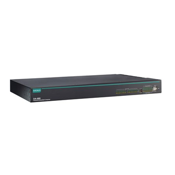
Page 6: Appearance
Appearance Front View Rear View Dimensions DA-680 Series Hardware User Manual... -
Page 7: Features
5 USB ports for connecting high-speed peripherals 8 or 16 isolated RS-485 ports • Supports both 100 to 240 VAC and 100 to 240 VDC power inputs • (single power and dual-power models available) Hardware Block Diagram DA-680 Basic System DA-680 Series Hardware User Manual... -
Page 8: Hardware Specifications
Hardware Specifications NOTE The latest specifications for Moxa’s products can be found at https://moxa.com. DA-680 Series Hardware User Manual... -
Page 9: Hardware Installation
Attach the left rack-mounting ear to the left Attach the other rack-mounting ear to the side of the DA-680 computer and secure the right side of the computer and secure it with four screws. the four screws. DA-680 Series Hardware User Manual... -
Page 10: Wiring Requirements
External metal parts of this equipment are extremely hot!! Before touching the equipment, you must take special precautions to protect your hands and body from serious injury. DA-680 Series Hardware User Manual... -
Page 11: Connecting The Power
Connecting the Power The DA-680 Series includes single-power and dual-power models that use terminal block(s) located on the rear panel. Connect the power cord wires to the screws on the power input and then tighten the screws. The Power LED will light up to indicate that power is being supplied to the DA-680, after which the BIOS will initialize the flash disk module, causing the Storage LED to blink. -
Page 12: Grounding The Chassis
If protective earthing is used as a safeguard, the instructions shall require connection of the equipment protective earthing conductor to the installation protective earthing conductor (for example, by means of a power cord connected to a socket-outlet with earthing connection). DA-680 Series Hardware User Manual... -
Page 13: Reset Button
Not operating, or in 10 Mbps Ethernet mode Green Serial port is transmitting data Serial Port TX 1-12 Not operating Yellow Serial port is receiving data Serial Port RX 1-12 Not operating Programmable 1-6 Green Defined by user DA-680 Series Hardware User Manual... -
Page 14: Connecting To Displays
You can use a USB dongle kit to secure your USB dongle inside your DA-680 computer. The USB dongle kit includes a USB plate and a screw. NOTE The USB dongle kit is an optional accessory that can be purchased separately. DA-680 Series Hardware User Manual... -
Page 15: Serial Ports
Put back the top cover of the computer. Serial Ports The DA-680 comes with 10 serial ports that support RS-485 mode that use terminal blocks. The pin assignments are printed on the rear cover of the product for your reference. DA-680 Series Hardware User Manual... -
Page 16: Gigabit Lan Ports
The DA-680 is provided with a relay output located on the rear panel of the computer. The default setting is N.O. If you want to change N.O. to N.C., you should open the case and switch the jumper. DA-680 Series Hardware User Manual... -
Page 17: Upgrading The Memory Module
NOTE If a memory module is already installed in the slot, push the two fasteners to free the module and then remove the module. DA-680 Series Hardware User Manual... -
Page 18: Installing A Msata Storage Card
Unfasten the screws on the top of the computer, and then take off the top cover. Find the location of the mSATA slot. Insert the mSATA storage card into the slot and fasten the two screws to secure the card to the slot. DA-680 Series Hardware User Manual... -
Page 19: Installing Sata Hard Disks
Disconnect the DA-680 from its power source. Unfasten the screws on the top of the computer, and then take off the top cover. Find SATA HDD/SSD location. Remove screw and install 3 copper pillars as follow: DA-680 Series Hardware User Manual... - Page 20 Place the SATA disk on the tray. Ensure that the SATA disk aligns with the screws on the storage tray. Put this tray on the pillars and screw. Connect the cable to the PCB board as follow: DA-680 Series Hardware User Manual...
-
Page 21: Bios Setup
When you enter Setup Utility, a basic description of each function key is listed at the bottom of the screen. General Help Select Item ↑↓. F5/ F6 Change Values Select Menu ←→ Setup Defaults Exit Save and Exit Select or go to Submenu. EN TER DA-680 Series Hardware User Manual... - Page 22 The BIOS configuration screen will be shown when you enter the Setup Utility option, as shown in the following figure. NOTE The Processor Type information will vary depending on the computer model that you have purchased. DA-680 Series Hardware User Manual...
-
Page 23: Administer Secure Boot
Please set as “enabled” in “Restore Secure Boot to Factory Settings” under Administer Secure Boot menu. Press F10 as save and exist. Moxa has included the Microsoft key in the BIOS by default. If you cannot boot up the computer using a non-Windows OS, use the following examples. DA-680 Series Hardware User Manual... -
Page 24: Enroll Efi Image
Enter into “DB OPTION” and enroll your key. Please make sure your key is CRT format and use RSA 2048 or better. Main Page The Main page displays basic system hardware information, such as model name, BIOS version, and CPU type. DA-680 Series Hardware User Manual... -
Page 25: Advanced Settings
Advanced Settings Select the Advanced tab in the BIOS setup utility to open the advanced features screen. DA-680 Series Hardware User Manual... -
Page 26: Boot Configuration
Boot Configuration This item allows users to configure the default value of Numlock. Options: On (default), Off. DA-680 Series Hardware User Manual... -
Page 27: Sata Configuration
The host drive controller can be configured for AHCI (default) or Intel RST Premium mode. SATA Speed Options: Gen 1, Gen 2, Gen 3 (default) Serial ATA Port This setting displays information on the drives installed on your computer. DA-680 Series Hardware User Manual... - Page 28 This item allows you to enable/disable hot-plugging capabilities (the ability to remove the drive while the computer is running) for the storage drives installed. Options: Disabled (default for Port 0), Enabled (default for Port 1) DA-680 Series Hardware User Manual...
-
Page 29: Intel Rapid Storage Technology
This option allows users to configure the Intel® Rapid Storage Technology. To configure the Intel Rapid Storage Technology settings, select the Device Management option when setting the Intel RST Premium mode, or saving changes and rebooting the computer. DA-680 Series Hardware User Manual... -
Page 30: Cpu Configuration
This feature makes the processor resources work more efficiently, enabling multiple threads to run on each core. It also increases processor throughput, improving overall performance on threaded software. Options: Disabled, Enabled (default) Turbo Mode Enable/Disable processor Turbo Mode. Options: Disabled, Enabled (default) DA-680 Series Hardware User Manual... -
Page 31: Video Configuration
2D/3D graphics performance. DVMT Total Gfx Mem This option allows you to configure the maximum amount of memory DVMT will use when allocating additional memory for the internal graphics device. Options: 256 MB (default), 128 MB, Max. DA-680 Series Hardware User Manual... -
Page 32: Chipset Configuration
System will load the default when RTC battery loss is detected. Options: Disabled, Enabled (default) DO-0 Level This option allows users to set the DO-0 level. Options: High (default), Low DO-1 Level This option allows users to set the DO-1 level. Options: High (default), Low DA-680 Series Hardware User Manual... -
Page 33: Sio Ite8786E
SIO ITE8786E This option allows users to configure serial port settings. Hardware Monitor This option allows users to view stats on the computer such as CPU and system temperature, voltage levels, and other chipset information. DA-680 Series Hardware User Manual... -
Page 34: Security Settings
This item indicates if the system has a TPM module configured and provides information on its type. TPM State This item allows users to view the current TPM settings. Clear TPM This item allows users to remove all TPM context associated with a specific owner. DA-680 Series Hardware User Manual... -
Page 35: Set Supervisor Password
To delete the password, select the Set Supervisor Password option and enter the old password; leave the new password fields blank, and then press enter. After setting the supervisor password, users can choose when the input password screen will pop up. DA-680 Series Hardware User Manual... -
Page 36: Power Settings
Options: Disabled (default); By Every Day (user specifies a regular daily time when the computer will power up); By Day of Month (user specifies a regular day each month when the computer will power up) DA-680 Series Hardware User Manual... -
Page 37: Boot Settings
Used to enable or disable boot-up from USB devices. Options: Enabled (default), Disabled Timeout This option allows users to set the number of seconds that the firmware will wait before booting the system with the default boot selection. DA-680 Series Hardware User Manual... -
Page 38: Efi
This option allows you to exit without saving any changes that might have been made to the BIOS. Options: Yes (default), No Load Optimal Defaults This option allows you to revert to the factory default BIOS values. Options: Yes (default), No DA-680 Series Hardware User Manual... -
Page 39: Load Custom Defaults
Incorrect BIOS updates may permanently damage the computer. We strongly recommend that you contact the Moxa technical support team for assistance to obtain all the necessary tools and the most current information before attempting to upgrade the BIOS on any Moxa device. DA-680 Series Hardware User Manual... - Page 40 Step 1: Create a Bootable USB Disk Before upgrading the BIOS, you must create a bootable USB drive for the system. Search for “format” and select Create and format hard disk partitions. DA-680 Series Hardware User Manual...
- Page 41 You must use the BIOS upgrade installation file to upgrade the BIOS. Contact Moxa’s technical department for assistance. Get the BIOS upgrade file (includes an efi folder and an xxxx.efi file) Copy the efi folder and xxxx.efi file to the bootable USB disk. DA-680 Series Hardware User Manual...
- Page 42 In the SHELL environment console, type fs0:, then go to the directory where the upgrade file is located and type xxxxxx.efi (the name of the file is based on the upgrade file you get from Moxa). The upgrade program will run automatically. Wait for the process to complete. DA-680 Series Hardware User Manual...
- Page 43 Access each device path fsx (x is the device index), then type ls to view the content of the boot device until you located the upgrade file and run it. ATTENTION Do NOT switch off the power supply to the computer during the BIOS upgrade, since doing so may cause the system to crash. DA-680 Series Hardware User Manual...
-
Page 44: Safety Installation Instructions
Appropriate consideration of equipment nameplate ratings should be used when addressing this concern. (5) Reliable Grounding: Reliable grounding of rack-mounted equipment should be maintained. Particular attention should be given to supply connections other than direct connections to the branch circuit (e.g., by using power strips). DA-680 Series Hardware User Manual...
Need help?
Do you have a question about the DA-680 Series and is the answer not in the manual?
Questions and answers