
Related Manuals for Moxa Technologies DA-820C Series


Summary of Contents for Moxa Technologies DA-820C Series
- Page 1 DA-820C Series Embedded Computer User’s Manual Version 1.0, August 2019 www.moxa.com/product © 2019 Moxa Inc. All rights reserved.
- Page 2 DA-820C Series Embedded Computer User’s Manual The software described in this manual is furnished under a license agreement and may be used only in accordance with the terms of that agreement. Copyright Notice © 2019 Moxa Inc. All rights reserved.
-
Page 3: Table Of Contents
Table of Contents Introduction ............................1-1 Overview ............................1-2 Model Descriptions and Package Checklist ....................1-2 Appearance ............................1-4 Dimensions ............................1-5 Features ............................1-5 Hardware Block Diagram ........................1-6 DA-820C Basic System ........................ 1-6 Hardware Specifications ........................1-6 Hardware Installation ........................2-1 Installing Rackmount Ears ........................ - Page 4 Discard Changes ........................3-23 Enable AMT ............................3-23 Use AMT ............................3-26 Upgrading the BIOS .......................... 3-28 Safety Installation Instructions ......................A-1...
-
Page 5: Introduction
Introduction Thank you for purchasing a Moxa DA-820C industrial computer, a multi-functional embedded computer designed especially for IEC 61850-3 substation automation systems. This manual covers hardware installation, connector interfaces, and BIOS setup of the DA-820C. For software configuration and management, please refer to the user’s manual for your operating system. The following topics are covered in this chapter: ... -
Page 6: Overview
This robust, rack-mountable design provides the hardened protection needed for industrial environment applications. Model Descriptions and Package Checklist The DA-820C Series includes the following models: DA-820C-KL3-H-T: Intel® Core™ i3-7102E, 2C/2T, 2.1 GHz CPU, with 2x HDMI, 1x VGA, 4 Gigabit LAN •... - Page 7 DA-820C Series Introduction DA-820C-KLXM-H: Intel® Core™ Xeon E3-1505MV6, 4C/8T, 3 GHz CPU, with 2x HDMI, 1x VGA, 4 • Gigabit LAN ports, 2 RS/232/422/485 3-in-1 serial port, 2 PS/2 and 6 DI, 2 DO, 1 mSATA, 2 SATA, 5 USB, without RAM, mSATA and OS, single power -25 to 55°C temp.
-
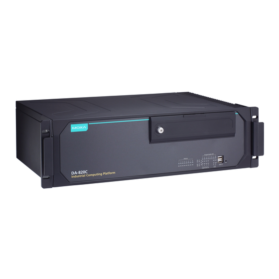
Page 8: Appearance
DA-820C Series Introduction Appearance Front View Rear View... -
Page 9: Dimensions
DA-820C Series Introduction Dimensions Unit = mm (inch) Features The DA-820C computer has the following features: • 7th Gen Intel® Core™ CPU (Kaby Lake) • 2 built-in DDR4 memory socket, up to total 32GB capacity • 2 x USB 2.0 and 3 x USB 3.0 type A ports for high-speed peripherals •... -
Page 10: Hardware Block Diagram
DA-820C Series Introduction Hardware Block Diagram DA-820C Basic System Hardware Specifications NOTE The latest specifications for Moxa’s products can be found at https://moxa.com. -
Page 11: Hardware Installation
Hardware Installation The DA-820C embedded computers are compact and rugged, making them suitable for industrial applications. The LED indicators allow users to monitor performance and identify trouble spots quickly, and multiple ports are provided for connecting a variety of different devices. The DA-820C embedded computers come with a reliable and stable hardware platform that lets you devote the bulk of your time to application development. -
Page 12: Installing Rackmount Ears
DA-820C Series Hardware Installation Installing Rackmount Ears The DA-820C computer comes with two Rackmount Ear Kits that allow users to install the computer on a rack. The Rackmount Ear Kit includes the following items. Follow these steps for the installation. -
Page 13: Wiring Requirements
DA-820C Series Hardware Installation Wiring Requirements The following common safety precautions should be observed before installing any electronic device: • Power wires and communication/signal wires should be routed through separate paths. If power and communication/signal wires must cross paths, make sure the wires are perpendicular at the intersection point. -
Page 14: Connecting The Power
DA-820C Series Hardware Installation Connecting the Power The DA-820C provides dual power inputs using a terminal block, which is located on the rear panel. Connect the power cord wires to the screws, and then tighten the screws. The Power LED will light up to indicate that power is being supplied to the DA-820C, after which the BIOS will initialize the flash disk module, causing the Storage LED to blink. -
Page 15: Grounding The Chassis
DA-820C Series Hardware Installation Grounding the Chassis There is a grounding connector located on the rear panel of the computer. Connect the connector to the chassis ground source. ATTENTION If protective earthing is used as a safeguard, the instructions shall require connection of the equipment protective earthing conductor to the installation protective earthing conductor (for example, by means of a power cord connected to a socket-outlet with earthing connection). -
Page 16: Reset Button
DA-820C Series Hardware Installation ATTENTION Equipment must be installed according to the applicable country’s wiring codes. In addition, there is a power button switch on the rear panel, which allows users to push to power on the computer again in case the computer is in the sleep or hibernate mode. -
Page 17: Led
DA-820C Series Hardware Installation There are 40 LED indicators on the front panel. Information about each LED indicator is given in the following table. Color Description Power Green Power is on No power input Storage Yellow/Blinking Data is being written to or read from the storage unit... -
Page 18: Connecting Usb Devices
DA-820C Series Hardware Installation For the pin definitions of the VGA connector, refer to the following figure and table. Pin No. Signal Definition GREEN BLUE DDC Data HSYNC VSYNC DDC Clock Connecting USB Devices The DA-820C comes with 2 USB 2.0 ports on the front panel and 3 USB 3.0 ports on the rear panel. The USB ports can be used to connect to other peripherals, such as flash drives for expanding the system’s storage... -
Page 19: Installing A Usb Dongle Kit
DA-820C Series Hardware Installation Installing a USB Dongle Kit You can use a USB Dongle Kit to secure your USB dongle inside your DA-820C computer. To install a USB Dongle Kit inside your DA-820C computer, do the following: NOTE The USB Dongle Kit is an optional accessory that can be purchased separately. -
Page 20: Gigabit Lan Ports
DA-820C Series Hardware Installation The ports use DB9 male connectors. Refer to the following table for the pin assignments: RS-232 RS-422 RS-485 RS-485 (4-wire) (2-wire) TxDA(-) TxDA(-) – TxDB(+) TxDB(+) – RxDB(+) RxDB(+) DataB(+) RxDA(-) RxDA(-) DataA(-) – – –... -
Page 21: Digital Inputs/Digital Outputs
DA-820C Series Hardware Installation Digital Inputs/Digital Outputs The DA-820C comes with six digital inputs and two digital outputs in a terminal block. Refer to the following figure for the location of the DI/DO connectors. For pin definitions and wiring methods, see the figures below. -
Page 22: Upgrading The Memory Module
DA-820C Series Hardware Installation Upgrading the Memory Module The DA-820C embedded computer supports 2 ECC registered DDR3 1333/1600 SODIMM modules, for up to 16 GB of memory (2 slots, each with 8 GB). To upgrade the SDRAM memory module, follow these instructions: 1. -
Page 23: Installing An Msata Storage Card
DA-820C Series Hardware Installation Installing an mSATA Storage Card The DA-820C embedded computer comes with an mSATA socket. To insert an mSATA storage card, follow these instructions. 1. Disconnect the DA-820C from its power source. 2. Unfasten the screws on the back of the computer, and then take off the upper cover. -
Page 24: Installing Sata Hard Disks
DA-820C Series Hardware Installation ATTENTION The DA-820C rackmount computer does not support the mSATA storage card hot swap and PnP (Plug and Play) functions. It is necessary to remove power source first before inserting or removing the mSATA storage card. - Page 25 DA-820C Series Hardware Installation 4. Place the SATA disk on the tray. 5. Turn back to the rear side of the tray, and fasten four screws. See the following diagram for details. 6. There are two plastic rails inside the slot. Make sure to insert the storage tray into the rails.
-
Page 26: Installing The Expansion Module
DA-820C Series Hardware Installation Installing the Expansion Module The DA-820C comes with an expansion socket, allowing users to install various expansion modules such as Gigabit Ethernet module and serial communication module. Follow these steps. 1. Unfasten the two screws on the module plate, and then remove the plate. -
Page 27: Inserting The Pcie/Pci Modules
DA-820C Series Hardware Installation Inserting the PCIe/PCI Modules The DA-820C computer comes with five slots supporting PCIe/PCI interfaces; users can install the modules for various industrial communications. Follow these steps. 1. Unfasten the screws on the rear panel and remove the upper cover. - Page 28 DA-820C Series Hardware Installation 3. To insert the module, remove the screw on the protection plate first, and then remove the plate. 4. Insert the module on the slot carefully. Make sure the module has been successfully inserted. 5. Fasten the screw on the module.
- Page 29 DA-820C Series Hardware Installation ATTENTION Please ensure to power off the computer first and then install/remove the PCIe/PCI modules. 2-19...
-
Page 30: Bios Setup
BIOS Setup This chapter describes the BIOS settings of the DA-820C computer. The BIOS is a set of input/output control routines for peripherals, and is used to initialize system peripherals before the operating system is loaded. The BIOS setup allows the user to modify the system configurations of these peripherals’ basic input/output. The following topics are covered in this chapter: ... -
Page 31: Entering The Bios Setup
DA-820C Series BIOS Setup Entering the BIOS Setup To enter the BIOS setup utility, press the “F2” key while the system is booting up. The main BIOS Setup screen will appear. Five options will be available: • Continue: Continue to boot up •... - Page 32 DA-820C Series BIOS Setup The BIOS configuration screen will be shown when you enter the Setup Utility option, as shown in the following figure. Note that the Processor Type information for will vary depending on which model you purchased.
-
Page 33: Main Page
DA-820C Series BIOS Setup Main Page The Main page displays basic system hardware information, such as model name, BIOS version, and CPU type. -
Page 34: Advanced Settings
DA-820C Series BIOS Setup Advanced Settings Select the “Advanced” option in the main menu to open the “Advanced Features” screen. NOTE The Active Management Technology is not supported in the KL3 models. -
Page 35: Boot Configuration
DA-820C Series BIOS Setup Boot Configuration This item allows users to configure the default value of Numlock. Options: On (default), Off. SATA Configuration The host drive controller can be configured for AHCI (default) or Intel RST Premium mode. - Page 36 DA-820C Series BIOS Setup Serial ATA Port This setting allows the user to display information about the installed drives. SATA Port—HotPlug This item allows you to enable/disable hot-plugging capabilities (the ability to remove the drive while the computer is running) for installed storage drives.
-
Page 37: Intel Rapid Storage Technology
DA-820C Series BIOS Setup From Device Management to configure the following Intel Rapid Storage Technology. Intel Rapid Storage Technology This section allows users to configure Intel® Rapid Storage Technology. -
Page 38: Cpu Configuration
DA-820C Series BIOS Setup CPU Configuration NOTE Hyper-Threading is not supported in the KL5 models. -
Page 39: Active Management Technology Support
DA-820C Series BIOS Setup Active Processor Cores This item indicates the number of cores to enable in each processor package. Hyper-Threading This feature makes the processor resources work more efficiently, enabling multiple threads to run on each core. It also increases processor throughput, improving overall performance on threaded software. -
Page 40: Video Configuration
DA-820C Series BIOS Setup Video Configuration This item allows you to configure the built-in Internal Graphics Device or external PCI Express Graphics card. Options: IGFX (default), PEG 3-11... - Page 41 DA-820C Series BIOS Setup Internal Graphics Device This option allows you to enable/disable the internal graphics device. Options: Enabled (default), Disabled IGD—DVMT Pre-Allocated This item allows you to configure pre-allocated memory capacity for the IGD. Pre-allocated graphics memory is invisible to the operating system.
- Page 42 DA-820C Series BIOS Setup PCI Express Graphic This option allows you to configure the external PCI Express Graphics card. PCIEx16-GEN X Set the PCIEx16 interface speed. The default is auto-detect. You can set a fixed speed for when a card cannot be detected.
-
Page 43: Chipset Configuration
DA-820C Series BIOS Setup Chipset Configuration This item allows you to configure the chipset settings. Power ON after Power Failure This item allows you to enable/disable the computer from automatically powering up after a system crash. Options: ON (default), OFF, Last State DO-0 Level This item allows users to set the DO 0 as high or low. -
Page 44: Sio Ite8786E
DA-820C Series BIOS Setup SIO ITE8786E This section allows users to configure serial port settings. Serial Port A This function allows users to configure the resources for serial port A. Disable: No resources Enable: User configures the resources Auto (default): EFI/OS chooses the resources Serial Port B This function allows users to configure the resources for serial port B. -
Page 45: Console Redirection
DA-820C Series BIOS Setup Hardware Monitor This item allows you to view stats such as CPU and system temperature, voltage levels, and other chipset information. The voltage values will vary depending on which model you purchased. There is a 5% tolerance for temperature values. -
Page 46: Security Settings
DA-820C Series BIOS Setup Security Settings This section allows users to configure security-related settings with a supervisor password and user password. Current TPM Device This item shows if the system has TMP device and its type. TPM State This item allows you view the status of current TPM settings. -
Page 47: Set Supervisor Password
DA-820C Series BIOS Setup Set Supervisor Password This item allows you to set the supervisor password. Select the Set Supervisor Password option and enter the password and confirm the password again. To delete the password, select the Set Supervisor Password option and enter the old password; leave the new password fields blank, and then press enter. -
Page 48: Power Settings
DA-820C Series BIOS Setup Enable: System will ask input password on post time. Disable: System will ask for the password to go to the setup utility. Config-Only: System will only ask for the password when you select the config (F2) option Power Settings The section allows users to configure power settings. -
Page 49: Power On Usb2 (Front)
DA-820C Series BIOS Setup Power On USB2 (Front) This item allows users to power on or power off the USB ports on the front panel. Options: Disabled, Enabled (default) Power On USB2 (Internal) This item allows user to powers on or power off the internal USB port inside the computer. -
Page 50: Boot Type
DA-820C Series BIOS Setup Boot Type This item allows you to enable/disable the quick boot function. Options: Dual Boot Type, Legacy Boot Type, UEFI Boot Type (default) Network Stack It deploys an Internet Protocol (IP) stack. The IP stack provides an application library to open/close connections to remote devices and send/receive data between the remote devices. -
Page 51: Exit Saving Changes
DA-820C Series BIOS Setup Exit Saving Changes This item allows you to exit the BIOS environment and save the values you have just configured. Options: Yes (default), No Save Change Without Exit This item allows you to save changes without exiting the BIOS environment. -
Page 52: Save Custom Defaults
DA-820C Series BIOS Setup Save Custom Defaults This item allows you to save the current BIOS values as a “custom default” that may be reverted to at any time by the “load custom defaults” selection just above. Options: Yes (default), No Discard Changes This item allows you to discard all settings you have just configured. - Page 53 DA-820C Series BIOS Setup 2. Press <Enter> to start the login procedure. 3. Type the default password: admin 3-24...
- Page 54 DA-820C Series BIOS Setup 4. Type the new password. It must include both upper-case and lower-case characters, numbers, and special symbols. E.g., Admin’12. 5. Select Intel® AMT Configuration to enable remote access without a local user present for consent, select User Consent, and then select User Opt-in and change the value to None.
-
Page 55: Use Amt
DA-820C Series BIOS Setup 7. Set Activate Network Access to enable remote access capability. Use AMT You can use any of the available AMT tools to execute the remote management function. The easiest method is using a web browser. 1. Type the IP for your DA-820C that was configured in the AMT configuration with port 16992. The AMT logon screen will appear. - Page 56 DA-820C Series BIOS Setup 2. Click on “Log On” and type the username (admin) and password to log in and control the DA-820C remotely. NOTE The DA-820C’s AMT port is LAN1. NOTE Refer to the Intel AMT Implementation and Reference Guide for details: https://software.intel.com/sites/manageability/AMT_Implementation_and_Reference_Guide/...
-
Page 57: Upgrading The Bios
DA-820C Series BIOS Setup Upgrading the BIOS This section describes how to upgrade the BIOS. However, note that it is easy to permanently damage the computer when upgrading the BIOS. We strongly recommend that you contact Moxa’s technical support staff for assistance in order to obtain all the necessary tools and the most current advice before attempting to upgrade the BIOS on any Moxa device. - Page 58 DA-820C Series BIOS Setup 2. Right click on the USB disk then select “Format”. 3. Select “FAT32”, and click OK to start formatting. 4. After formatting the USB disk, download the “Shell.efi”. 5. Link to “https://github.com/tianocore/edk2/branches”, select the latest branch.
- Page 59 DA-820C Series BIOS Setup 7. Copy the “bootX64.efi” to USB disk \efi\boot\bootX64.efi (Note: The folder should be created by absolute path as below). Step 2: Prepare the Upgrade File You must use the BIOS upgrade installation file to upgrade the BIOS. Contact Moxa’s technical department for assistance.
- Page 60 DA-820C Series BIOS Setup 3. Screen will be going into the SHELL environment, type fs0: then, go to the directory where the upgrade file is located, type :xxxxxx.efi (the name is based on the upgrade file you get from Moxa).
- Page 61 DA-820C Series BIOS Setup 7. Go each fsx (x means number), then type ls to view the content of the boot device. If find the upgrade file, execute it ATTENTION Do NOT switch off the power supply during the BIOS upgrade, since doing so may cause the system to crash.
-
Page 62: Safety Installation Instructions
Safety Installation Instructions A. RTC Battery Warning ATTENTION There is a risk of explosion if the wrong type of battery is used. To avoid this potential danger, always be sure to use the correct type of battery. Contact the Moxa RMA service team if you need to replace your battery.
Need help?
Do you have a question about the DA-820C Series and is the answer not in the manual?
Questions and answers