
Related Manuals for Kramer RC-7LC


Summary of Contents for Kramer RC-7LC
-
Page 1: User Manual
Kramer Electronics, Ltd. USER MANUAL Models: RC-7LC, Media / Room Controller RC-7LCE, Media / Room Controller... -
Page 2: Table Of Contents
Figures Figure 1: RC-7LC Front Panel Figure 2: RC-7LCE Front Panel Figure 3: Side Panel of the RC-7LC and RC-7LCE (Enlarged View) Figure 4: Side Panel of the RC-7LC and RC-7LCE Figure 5: RC-7LCE (Front Perspective) Configuration Figure 6: RC-7LCE (Rear Perspective) Configuration... -
Page 3: Introduction
IR learner 4 By authorized Kramer technical personnel or by an external system integrator (refer to the separate online guide) 5 That provides information about how to set up the system. This online guide may well be updated on a regular basis. For... -
Page 4: Getting Started
A/V equipment in any multimedia room, especially the control of a projector or other display device, via RS-232 and/or IR emitter cable. The RC-7LC / RC-7LCE is 12V DC fed. The RC-7LC is a one-gang wall plate. The RC-7LCE is two-gang wall plate intended for the European market. - Page 5 (often associated with low quality cables) Avoid interference from neighboring electrical appliances and position the RC-7LC / RC-7LCE away from moisture, excessive sunlight and dust Caution – No operator-serviceable parts inside unit.
-
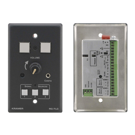
Page 6: Your Rc-7Lc / Rc-7Lce
2 Via the front panel, without having to remove the RC-7LC from its mounting 3 Letting you configure the RC-7LC directly from the remote transmitter without the need for software 4 In a clockwise direction to increase the volume; in a counter-clockwise direction to decrease the volume... -
Page 7: Defining The Rc-7Lce Front Panel
Your RC-7LC / RC-7LCE 4.2 Defining the RC-7LCE Front Panel Figure 2 and Table 2 define the RC-7LCE front panel: Figure 2: RC-7LCE Front Panel Table 2: RC-7LCE Front Panel Feature Function Mounting holes (4) For fastening the controller in place... -
Page 8: Defining The Rc-7Lc / Rc-7Lce Side Panel
Your RC-7LC / RC-7LCE 4.3 Defining the RC-7LC / RC-7LCE Side Panel Figure 3 illustrates an enlarged view of the side panel of the RC-7LC and RC-7LCE: Figure 3: Side Panel of the RC-7LC and RC-7LCE (Enlarged View) Figure 4 defines the side panel of the RC-7LC and RC-7LCE. For an... -
Page 9: Figure 4: Side Panel Of The Rc-7Lc And Rc-7Lce
, ! & ' 386, !54 & ) 3 % # '4 5+6 '* !+ ', , ) - '( ) & '( ) 7 # 8 1 ( !" # % / 0 Figure 4: Side Panel of the RC-7LC and RC-7LCE... -
Page 10: Using Your Media / Room Controller
RC-7LCE, and to the projector via IR or RS-232: Figure 5: RC-7LCE (Front Perspective) Configuration 1 From this section on, all the information is relevant to both the RC-7LCE and the RC-7LC, unless noted otherwise KRAMER: SIMPLE CREATIVE TECHNOLOGY... -
Page 11: Figure 6: Rc-7Lce (Rear Perspective) Configuration
Using Your Media / Room Controller The example in Figure 6 shows a rear view perspective of a typical RC-7LCE configuration. It connects to the power amplifier directly, and to the projector via RS-232, as well as to two relay items (a screen and a lighting system). -
Page 12: Figure 7: Example Of A Typical Setup In The Lecture Auditorium
Using Your Media / Room Controller Amplifier Figure 7: Example of a Typical Setup in the Lecture Auditorium KRAMER: SIMPLE CREATIVE TECHNOLOGY... -
Page 13: Operating The Rc-7Lc / Rc-7Lce
Using Your Media / Room Controller 5.1 Operating the RC-7LC / RC-7LCE In the example defined in Table 3, the buttons—ON, OFF, PC, DVD and VCR—are programmed by the system integrator to perform several tasks Table 3: The Commands Configuration ON Button Macro Sequence 1. -
Page 14: An Example Of Operating The Rc-7Lc / Rc-7Lce
Flash Memory Upgrade 5.3 An Example of Operating the RC-7LC / RC-7LCE Figure 8 shows an example of how to operate the RC-7LC / RC-7LCE: Select the DVD input on the projector and play the DVD. Select the PC input on the projector and resume the slide show. -
Page 15: Downloading From The Internet
Applet dat file, to a folder (for example, C:\Program Files\KFR Upgrade). 3. Install the KFR-Programmer Application. Connecting the PC to the RS-232 Port Before installing the latest Kramer Ethernet firmware version on the RC- LC, do the following: to the CONFIG port on the RC-7LC 1. -
Page 16: Technical Specifications
RC-7LCE: 15.1cm x 4.4cm x 8.6cm (5.94" x 1.75" x 3.39", W, D, H) WEIGHT: 0.3kg (0.67lbs) approx ACCESSORIES: Power supply, Windows -based Kramer control and configuration software OPTIONS: Dual IR emitter cable, single IR emitter cable, IR extension cable, CONFIG. cable... - Page 17 EXCLUSION OF DAMAGES The liability of Kramer for any effective products is limited to the repair or replacement of the product at our option. Kramer shall not be liable for: 1. Damage to other property caused by defects in this product, damages based upon inconvenience, loss of use of the product, loss of time, commercial loss;...
- Page 18 For the latest information on our products and a list of Kramer distributors, visit our Web site: www.kramerelectronics.com, where updates to this user manual may be found. We welcome your questions, comments and feedback. Safety Warning: Disconnect the unit from the power supply before opening/servicing.
Need help?
Do you have a question about the RC-7LC and is the answer not in the manual?
Questions and answers