Table of Contents
Advertisement
Quick Links
Thanks for purchasing Colorful 945 series motherboard:
The C.945PL is based on the latest Intel 945PL and ICH7. Support
dual-channel DDR2 400/533/667MHz memory, Other configurations-such as
hardware functions, interface, BIOS etc, are the same as C.945PL Ver2.1,so we
take C.945PL Ver2.1 as an example.
The C.945PL Ver2.1 motherboard supports the Intel® Pentium D/Core TM 2
Duo/ Pentium 4 / Celeron D CPU processors in the LGA775 socket with the
scalability for future processor innovations. Embedded AC'97 8-channel Audio
CODEC. It Provides RTL81100S Gigabit LAN /RTL8100C Megabit LAN
(optional) .
C.945PL Ver2.1 provides 3 PCI slots, 2 PCIE x16 slots, 1 PCIE x 1 slot
Packing Contents
1 Colorful C.NF5-DH Ver1.4 motherboard
1 SATA cable and 1 power cable
1 Standard Cable for IDE Devices
1 Driver/Utility CD
1 Warranty Card
1 User's Guide
C.945PL VER2.1
Chapter 1 Introduction
Advertisement
Table of Contents

Subscribe to Our Youtube Channel
Related Manuals for Colorful C.945PL


Summary of Contents for Colorful C.945PL
-
Page 1: Chapter 1 Introduction
Embedded AC’97 8-channel Audio CODEC. It Provides RTL81100S Gigabit LAN /RTL8100C Megabit LAN (optional) . C.945PL Ver2.1 provides 3 PCI slots, 2 PCIE x16 slots, 1 PCIE x 1 slot Packing Contents 1 Colorful C.NF5-DH Ver1.4 motherboard... - Page 2 ATI CrossFire Technology Introduction ATI released today its new technology that allows two video cards to be connected together in parallel in order to increase the system gaming performance – theoretically this technology can double it, called Crossfire. When two ATI cards are linked up, they are capable of using three different methods to split the rendering load between them—super tiling, scissor, and alternate frame rendering.
- Page 3 MOTHERBOARD SPEC - Supports Intel ® Pentium® D/ Core™2 Duo / Pentium® 4 / Celeron® D CPU in the LG5 A77socket - Supports FSB Frequency 533/800MHz(Intel® 945PL) - Supports FSB Frequency 533/800/1066MHz(Intel® 945P) - Supports Hyper-Threading Chipset - North Bridge: Intel ® 965PL/ Intel® 945P - South Bridge: ICH7 Main Memory - Supports 2 DIMM of 240-pin 1.8 Volt DDR2 SDRAM...
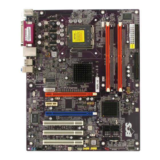
- Page 4 C.945PL/945P VER2.1 Motherboard Layout...
- Page 5 Motherboard Parts schedule Part Description PCIE_16X&PCIE1 Graphics Cards Slot PCI Express x16 PCIE1 PCI Express x1 Slot PCI Express x1 PCI1-PCI3 3 x 32bit PCI Slots PCI Slots CPU_FAN CPU Fan Connector 4 PIN Power ATX ATX Power Connector 24PIN ATX_12V P4 ATX Power Connector 4PIN...
-
Page 6: Chapter 2 Hardware Installation
5. Connect IDE and Floppy cables, ATX Power cable, Front Panel /Back Panel cable Step 1: Install CPU The C.945PL Ver2.1 motherboard supports the Intel® Pentium D/Core TM 2 Duo/ Pentium 4 / Celeron D CPU processors in the LGA775 socket . - Page 7 c. Install the cooler. Connect the power cable to the CPU_FAN connector. NOTE: After installing the system, please check and set the CPU frequency. Step 2: Install Memory The motherboard provides 4 slots for 240-pin DDR2 DIMM, which supports dual-channel DDR2 533/667/800MHz. The clock can be set in BIOS.
- Page 8 The plastic clip at each side of the DIMM slot will automatically close. Install Dual-channel C.945PL Ver2.1 motherboard supports dual-channel DDR2 533/667/800MHz memory interface, while both channels (in different color) populated with same amount of memory size will work as dual-channel DDR.
- Page 9 You can clear CMOS by shorting 2-3 pin. Before you clearing the CMOS, following next procedure: 1. Shut down your computer 2. Pull out the ATX power cable 3. Shorting 2-3 pin 3 seconds 4. Then shorting the 1-2 pin 5.
- Page 10 Pin 1-2 close 1-2 Support power on by keyboard Pin 2-3 close 2-3 Disable the power on by keyboard LAN Control: JLAN Pin 1-2 close 1-2 Disable LAN Pin 2-3 close 2-3 Enable LAN...
- Page 11 Connectors Floppy Disk Dive Connector:FDD1 The motherboard provides a standard 34pin floppy disk drive connector that can supports 2 floppy drives. There is also a foolproof design on pin 34 to avoid wrong installation. Connect the floppy disk ribbon cable After connecting the single plug end to J23 on the motherboard, connect the two plugs at other end to the floppy drive(s).
- Page 12 IDE1 is a 40 pin connector which can connect 2IDE devices and support ATA33/66/100. We suggest you to set the HDD to Master and the CD-ROM to Slave. Serial ATA Connectors: SATA1-SATA4...
- Page 13 You can use these connectors to install Serial ATA hard disks. USB Port Headers: USB2/USB3 The header is used for connecting 2 additional USB 2.0/1.1 ports plug. Line-Out, MIC Header: F_AUDIO These headers connect to Front Panel Line-out, MIC connector with cable.
- Page 14 Symbol Symbol Power FrontAudio(R) RearAudio(R) Empty No Pin F_Audio_AC97 FrontAudio(L) RearAudio(L) Front Audio Jack FAN Power Heads: AUXF AN1&SYS AN1 These two fan heads is very important in you installation. It’s the power supply of the fan which to reduce the system and the CPU temperature.
- Page 15 NOTE: We suggest you to install cooler on the CPU and connect the power cable to the J13 connector. CD Audio-In Headers: CN_IN1 CN_IN1 is the connector for CD-Audio Input signal. Please connect it to CD-ROM, TV, or MPEG card Audio output connector.
- Page 16 IR infrared module Headers: IR1 Infrared Module Headers CLOSE OPEN...
- Page 17 Front Panel Switch, LEDs and Speaker connector: FPIO2 SPEAKER1: Speaker connector This 4-pin connector connects to the case-mounted speaker. You should follow the instruction of the speaker cable. HD-LED: Primary/Secondary IDE LED When the IDE hard disks are written, this LED will shine. RESET: Reset switch This connector connects to the case-mounted reset switch for rebooting your computer without having to turn off your power switch.
- Page 18 Power Connector: ATX Install PCI Express x16 Graphics Card(s)
- Page 19 This motherboard provides 2x PCI-E 16X slots and 1X PCI-E 1X slot, supports single PCI Express x16 graphics card, 2 pieces NVIDIA SLI graphics cards or 2 pieces ATI Crossfire graphics cards. If you have a single graphics card, please insert it in PCIE16XP1;if you want to install a SLI platform, please insert two SLI ready graphics cards to the 2 PCI-E 16X slots, and then you need to install the SLI bridge;...
- Page 20 Back panel connectors Mouse/Keyboard Connector, USB ports, Serial Port Connector (COM1), LAN (RJ-45) Jack, Parallel Port Connector, MIC_IN Jack, LINE_IN Jack, LINE OUT Jack, etc. Parts PS/2 Mouse Connector This connector is for a PS/2 mouse. PS/2 Keyboard Connector This connector is for a PS/2 keyboard. PRN Connector This connector is for the printer, scanner or other parallel devices...
-
Page 21: Chapter 3 Drivers Installation
Chapter 3 Drivers installation Insert CD into your CD-ROM drive and a menu should appear as below. The Driver CD include an auto detect software which can tell you what type the chipset, AC97, integrate VAG or integrate LAN is, you can click the button on the menu to install the drivers. - Page 22 Audio driver: X:\audio\alc\setup.exe Integrate LAN: X:\lan\rtl\setup.exe NOTE: The chipset manufacturer update the drivers frequency in order to improve the capability and compatibility, we try our best to keep the latest drivers in the drivers want update drivers please give attention website(http://tec.colorful.cn/).
-
Page 23: Chapter 4 Bios Setup
Chapter 4 BIOS Setup The items under each BIOS category described in this chapter are under continuous update for better system performance. Therefore, the description may be slightly different from the latest BIOS and should be held for reference only. The data that CMOS SETUP is saved in the integrate CMOS SRAM on the motherboard. - Page 24 Menu allows you to select from 14 setup functions and two exit choices. Use arrow keys to select among the items and press <Enter> to accept or enter the sub-menu. Phoenix – Award WorkstationBIOS CMOS Setup Utility Standard CMOS Features Colorful Magic Control Advanced BIOS Features Load Fail-Safe Default Advanced Chipset Features...
-
Page 25: Standard Cmos Features
Set Supervisor Password This entry for setting Supervisor password. Set User Password This entry for setting User password. Save & Exit Setup Save CMOS value changes to CMOS and exit setup. Exit Without Saving Abandon all CMOS value changes and exit setup. Standard CMOS Features The items in Standard CMOS Setup Menu are divided into several categories. - Page 26 NOTE: specifications of your drive must match with the drive table. The hard disk will not work properly if you enter improper information for this category. If the type of hard disk drives is not matched or listed, you can use Manual to define your own drive type manually.
-
Page 27: Advanced Bios Features
Advanced BIOS Features In this menu, you can set several basic functions. Some items are necessary to set; others if you set right, the system will work more efficient. Phoenix – Award BIOS CMOS Setup Utility Advanced BIOS Features Item Help ↑... -
Page 28: Cpu L1 & L2 Cache
CPU L1 & L2 Cache Enable or Disable the L1 & L2 cache which is built in the processor. Available options: [Enabled],[Disabled] CPU L3 Cache The L3 cache is among the processor and memory which is built in the motherboard. L3 is slower than L1 or L2.This option for enable or disable the L3 cache. -
Page 29: Apic Mode
Typematic Rate Setting Keystrokes repeat at a rate determined by the keyboard controller. When enabled, the typematic rate and typematic delay can be selected. Available options: [Enabled], [Disabled] Typematic Rate (Char s/Sec) Sets the number of times a second to repeat a keystroke when you hold the key down. The settings are: 6, 8, 10, 12, 15, 20, 24, and 30. -
Page 30: Advanced Chipset Features
Advanced Chipset Features Phoenix – Award BIOS CMOS Setup Utility Advanced Chipset Features DRAM Timing Selectable By SPD Item Help Menu Level CAS Latency Time Auto DRAM RAS# to CAS# Delay Auto DRAM RAS# Precharge Auto Precharge dealy <tRAS> Auto Sysetm Memory Frequency Auto Sysetm BIOS Cacheable... -
Page 31: Peg Force X1
System Memory Frequency Available options: [Auto],[400],[533],[667] System BIOS Cacheable Selecting Enabled allows caching of the system BIOS ROM at F0000h-FFFFFh, resulting in better system performance. However, if any program writes to this memory area, a system error may result Available options: [Enabled], [Disabled] Video BIOS Cacheable Select Enabled allows caching of the video BIOS, resulting in better system performance. -
Page 32: Ide Hdd Block Mode
OnChip IDE Device Press <Enter> to enter the sub-menu and the following screen appears: Phoenix – AwardBIOS CMOS Setup Utility Onchip IDE Device Item Help IDE HDD Block Mode Enabled IDE DMA transfer access Disabled Menu Level On-chip Primary PCI IDE Enabled IDE Primary Master PIO Auto... - Page 33 Available options: [Enabled], [Disabled] IDE Secondary Master / Slave PIO The four IDE PIO (Programmed Input/Output) fields let you set a PIO mode (0-4) for each of the four IDE devices that the onboard IDE interface supports. Modes 0 through 4 provide successively increased performance. In Auto mode, the system automatically determines the best mode for each device.
- Page 34 [Enabled] enables the system to support USB 2.0 spec. Available options: [Enabled], [Disabled] USB Keyboard Support Select [Enabled] if your system contains a Universal Serial Bus (USB) controller and you have a USB keyboard. Available options: [Enabled], [Disabled] USB Mouse Support Select [Enabled] if your system contains a Universal Serial Bus (USB) controller and you have a USB mouse.
-
Page 35: Pwron After Pwr-Fail
choosing [ECP], the onboard parallel port will operate in ECP mode only. Choosing [ECP + EPP] will allow the onboard parallel port to support both the ECP and EPP modes simultaneously. PWRON After PWR-Fail This item is for setting the computer state after a power cut. Setting [ON] will boot up automatically. -
Page 36: Run Vgabios If S3 Resume
S1<POS> (default) The S1 sleep mode is a low power state. In this state, no system context is lost (CPU or chipset) and hardware maintains all system contexts. S3<STR> The S3 sleep mode is a lower power state where the in formation of system configuration and open applications/files is saved to main memory that remains powered while most other hardware components turn off to save energy. -
Page 37: Soft-Off By Pwr-Bttn
Available options: [Disabled], [1Min 15Min] Soft-Off by PWR-BTTN Pressing the power button for more than 4 seconds forces the system to enter the Soft-Off state. Available options: [Delay 4 Sec], [Instant-Off] CPU THRM-Throttling This option allows you to adjust the CPU temperature. If the CPU temperature gets to the temperature you set, CPU frequency will be throttling. -
Page 38: Init Display First
settings. Phoenix – Award BIOS CMOS Setup Utility PnP/PCI Configurations Init Display First PCI Slot Item Help Reset Configuration Data Disabled Menu Level Resources Controlled By Auto(ESCD) IRQ Resources Press Enter PCI/VGA Palette Snoop Disabled INT Pin 1 Assignment Auto INT Pin 2 Assignment Auto INT Pin3 Assignment... -
Page 39: Pc Health Status
Select + / - / PU / PD value save Exit General Help Previous Values Fail-Safe Defaults Optimized Defaults Colorful Magic Control Phoenix – Award WorkstationBIOS CMOS Setup Utility Colorful Magic Control CPU Clock Ratio Item Help Auto Detect PCI Clk Spread Spectrum Disabled... - Page 40 CPU Clock Ratio This setting is for adjusting the CPU Clock Ratio. Auto Detect PCI Clk This setting allows auto detect PCI slots. When select [Enabled], the PCI clock will be disabled in order to reduce the EMI. Available options: [Enabled] Spread Spectrum If you do not have any EMI problem, leave the setting at [Disabled] for optimal system stability and performance.
-
Page 41: Load Fail-Safe Defaults
Load Fail-Safe Defaults The option on the main menu allows users to restore all of the BIOS settings to the default Optimized values. The Optimized Defaults are the default values set by the motherboard manufacturer specifically for optimal performance of the motherboard. When you select Load Optimized Defaults and press <Enter>, a message as below appears: Phoenix –... -
Page 42: Set Supervisor Password
Set Supervisor Password This prevents an unauthorized person from changing any part of your system configuration. If you want to be prompted to enter it every time you try to enter Setup, please select Setup in Advanced BIOS Features; If you want to be prompted to enter it every time you try to enter System, please select System in Advanced BIOS Features. -
Page 43: Set User Password
Set User Password This can only enter but do not have the right to change the options of the setup menus. If you want to be prompted to enter it every time you try to enter Setup, please select Setup in Advanced BIOS Features; If you want to be prompted to enter it every time you try to enter System, please select System in Advanced BIOS Features. -
Page 44: Exit Without Saving
Type <Y> and press <Enter>, all the settings will store in CMOS and the system will be rebooted. If you want to change the settings, press <Del> after POST. Exit Without Saving If you don't want to store the settings that you change, please select Exit Without Saving and press <Enter>, a message as below appears: Phoenix –...
Need help?
Do you have a question about the C.945PL and is the answer not in the manual?
Questions and answers