
Related Manuals for Colorful C.B250A-BTC V20


Summary of Contents for Colorful C.B250A-BTC V20
- Page 1 C.B250A-BTC V20 User’s Manual Motherboard Colorful Technology Website: http://www.colorful.cn...
- Page 2 Copyright This motherboard manual belongs to Colorful Technology and Development CO, LTD. No one is permitted to copy, change, or translate without our written permission. Disclaimer The products name we mentioned in this manual is only for identifying, all of the brands belong to other company.
- Page 3 1. Introduction Thanks for purchasing our based on Intel B250 Chipset motherboard. The motherboard C.B250A-BTC V20 based on Intel B250 Express Chipset, support Intel LGA1151 CPUs, support dual channel DDR4 2400/2133MHZ memory, support PCI-E 3.0 standard。 The motherboard provides 1*HDMI port、1*VGA port、1*DVI port、...
- Page 4 1.2. MOTHERBOARD SPEC Support Intel LGA1151 CPUS Intel B250 Chipset Main Memory Dual-Channel DDR4 2400/2133MHZMHz support Offer 2 DIMM slots Slots 1*PCI Express 3.0x16 slot 5*PCI Express x1 slots 6*UPCIE slots Storage 5*SATA3.0 6Gb/s ports 6*USB2.0+6*USB3.0 Rear IO 1*PS/2 Mouse/ Keyboard port Connector 1*LAN(RJ45) port 2*USB 2.0 ports...
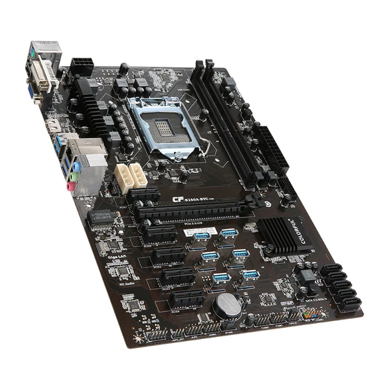
- Page 5 1.3. Motherboard Layout...
- Page 6 1.PS/2 Mouse/ Keyboard port and USB2.0 ports 2.Connect to VGA+DVI monitor 3.Connect to HDMI monitor 4.Connect to USB3.0 devices 5.Connect to USB3.0 devices and LAN 6.Audio devices 7.8-pin ATX 12V Power connector 8.CPU Fan connector 9.Intel LGA1151 socket 10.DIMM slots 11.24-pin ATX Power connector 12.USB 3.0 header 13.SATA3.0 port...
- Page 7 2. Hardware Installation This section will guide you through the installation of the motherboard. The topics covered in this section are: Preparing the motherboard Installing the CPU Installing the CPU fan Installing the memory Installing the motherboard Connecting cables and setting switches 2.1.
- Page 8 7. Close the load plate over the CPU and press down while you close and engage the socket lever. 8. There are many different fan types that can be used with this motherboard. Follow the instruction that came with you fan assembly. Be sure that the fan orientation is correct for your chassis type and your fan assembly.
- Page 9 2.3. Installing Memory DIMMs Your new motherboard has 2 slots for DDR4 memory. They support dual channel DDR4 memory technology. There must be at least one memory bank populated to ensure normal operation. Use the following the recommendations for installing memory. 1 DIMM: Install into DIMM1.
- Page 10 shield and secure the motherboard into the chassis. Be sure that the CPU fan assembly has enough clearance for the chassis covers to lock into place and for the expansion cards. Also make sure the CPU Fan assembly is aligned with the vents on the covers. 2.5.
- Page 11 8-pin ATX 12V power Internal Headers Front panel USB Headers Audio Serial ATA III Chassis Fans Rear panel USB 2.0 Adapter Expansion slots 2.7.1. ATX power connectors (24-pin ATXPWR, 8-pin ATX12V) These connectors are for an ATX power supply. The plugs from the power supply are designed to fit these connectors in only one orientation.
- Page 12 2.7.3. Back Panel IO Connector Parts PS/2 Mouse This connector is for a PS/2 mouse. Connector PS/2 Keyboard This connector is for a PS/2 keyboard. Connector LAN Jack The standard RJ-45 jack is for connection to single Local Area Network (LAN). You can connect a network cable to it.
- Page 13 HDMI Onboard HDMI port, connect to HDMI Monitor USB Ports These connectors are for attaching USB devices such as keyboard, mouse, or other USB-compatible devices. 2.7.4. USB 3.0 connectors This connector is for USB 3.0 devices. 2.7.5. USB2.0 connectors These connectors are for USB 2.0 ports. Connect the USB module cable to any of these connectors, then install the module to a slot opening at the back of the system chassis.
- Page 14 2.7.6. F_AUDIO(Front panel audio connector) This connector is for a chassis-mounted front panel audio I/O module that supports either High Definition Audio or AC`97 audio standard. Connect one end of the front panel audio I/O module cable to this connector. 2.7.7.
- Page 15 System power LED (2-pin PLED) This 2-pin connector is for the system power LED. Connect the chassis power LED cable to this connector. The system power LED lights up when you turn on the system power, and blinks when the system is in sleep mode. Hard disk drive activity LED (2-pin IDE_LED) This 2-pin connector is for the HDD Activity LED.
- Page 16 2.7.9. SPDIF header: JSPD_OUT This SPDIF header is for SPDIF audio devices 2.7.10. Debug header:JLPC This Debug header is for Debug serial devices...
- Page 17 2.7.11. COM header:JCOM1 This COM header is for COM serial devices 2.7.12. Clear CMOS Jumper: CLR_CMOS There is a CMOS RAM on board that has a power supply from external battery to keep the system configuration data. With the CMOS RAM, the system can automatically boot OS every time it is turned on.
- Page 18 You can clear CMOS by shorting 1-2 pin. Before you clearing the CMOS, following next procedure: 1. Turn off the AC power supply and connect pins 1 and 2 together using the jumper cap. 2. Return the jumper setting to normal (pin 2 and 3) or Remove the jumper 3.
- Page 19 Formatiert: (Asiatisch) Chinesisch (VR China) Copyright Notice The material in this document is the intellectual property of Colorful Technology and Development CO, LTD. We take every care in the preparation of this document, but no guarantee is given as to the correctness of its contents.
- Page 20 Product SN ___ Dealer name___ Dealer phone ___ Dealer address ___ Website: www.colorful.cn Service hotline: +86400-678-5866 Entering BIOS Setup Power on the computer and the system will start the Power On Self Test (POST)process. When the message below appears on the screen, press <DEL>...
- Page 21 Main Advanced Chipset Security Boot C.Oclock Boot Configuration Setup Prompt Timeout Bootup Numlock State →←Select Screen Full LOGO Display Enabled Up/Down:Choose Item Enter/ Click: Select +/-: Change Opt Boot Option Priorities F1: General Help Boot Option #1 F7: Previous Values Boot Option #2 Optimized Defaluts...
Need help?
Do you have a question about the C.B250A-BTC V20 and is the answer not in the manual?
Questions and answers