
Subscribe to Our Youtube Channel
Related Manuals for Colorful C.H81A-BTC V20


Summary of Contents for Colorful C.H81A-BTC V20
- Page 1 C.H81A-BTC V20 User’s Manual Motherboard Colorful Technology Website: http://www.colorful.cn...
- Page 2 Copyright This motherboard manual belongs to Colorful Technology and Development CO, LTD. No one is permitted to copy, change, or translate without our written permission. Disclaimer The products name we mentioned in this manual is only for identifying, all of the brands belong to other company.
-
Page 3: Packing Contents
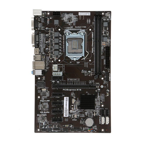
1. Introduction Thanks for purchasing our based on INTEL H81 Express Chipset motherboard. C.H81A-BTC V20 motherboard based on Intel H81 Express Chipset, support processors, support dual channel Intel LGA1150 Haswell DDR3 memory, support PCI-E 2.0 standard。 1066 /1333/1600MHz The motherboard provides 1* port、... - Page 4 1.2. C.H81A-BTC V20 MOTHERBOARD SPEC Intel LGA1150 Haswell support processors Chipset Intel H81 1600/ Main Memory Dual-Channel 1333/1066MHz support Offer 2 DIMM slots Slots 1 PCI-Express 2.0 x16 slot 5 PCI-Express 2.0 x1 slot Storage 2*SATA2.0&2*SATA3.0 port 8*USB2.0 Rear IO...
- Page 5 1.3. C.H81A-BTC V20 Motherboard Layout...
- Page 8 2 x PS/2 Mouse/ Keyboard port Connect to VGA monitor Connect to DVI monitor Connect to HDMI monitor 5. Connect to USB devices 6. Connect to LAN and USB devices 7. Audio devices 8.JKB Jumper . CPU Fan connector 10. 8-pin ATX 12V Power connector LGA 1150 socket 12 for PCIE VGA CARD power supply 13 for 4-pin PCIE VGA CARD power supply...
-
Page 9: Hardware Installation
2. Hardware Installation This section will guide you through the installation of the motherboard. The topics covered in this section are: Preparing the motherboard Installing the CPU Installing the CPU fan Installing the memory Installing the motherboard Connecting cables and setting switches 2.1. - Page 10 7. Close the load plate over the CPU and press down while you close and engage the socket lever. 8. There are many different fan types that can be used with this motherboard. Follow the instruction that came with you fan assembly. Be sure that the fan orientation is correct for your chassis type and your fan assembly.
-
Page 11: Installing Memory Dimms
2.3. Installing Memory DIMMs Your new motherboard has 2 slots for DDR3 memory. They support dual channel DDR3 memory technology. There must be at least one memory bank populated to ensure normal operation. Use the following the recommendations for installing memory. One DIMM: Install into DIMM 1. -
Page 12: Securing The Motherboard Into The Chassis
make all the connections. Use the following procedure to install the I/O shield and secure the motherboard into the chassis. Be sure that the CPU fan assembly has enough clearance for the chassis covers to lock into place and for the expansion cards. Also make sure the CPU Fan assembly is aligned with the vents on the covers. - Page 13 24-pin ATX power 8-pin ATX 12V power Internal Headers Front panel USB Headers Audio Serial ATA II Chassis Fans Rear panel USB 2.0 Adapter Expansion slots 2.7.1. ATX power connectors (24-pin ATXPWR, 8-pin ATX12V) These connectors are for an ATX power supply. The plugs from the power supply are designed to fit these connectors in only one orientation.
- Page 14 The system may become unstable or may not boot up if the power is inadequate. 2.7.2. Serial ATA 3.0/6.0 Gb/s connectors (7-pin) These connectors connect to Serial ATA 3.0/6.0 Gb/s hard disk drives and optical drives via Serial ATA 3.0/6.0 Gb/s signal cables. 2.7.3.
- Page 15 Parts PS/2 Mouse This connector is for a PS/2 mouse. Connector PS/2 Keyboard This connector is for a PS/2 keyboard. Connector LAN Jack The standard RJ-45 jack is for connection to single Local Area Network (LAN). You can connect a network cable to it.
- Page 16 2.7.5. USB2.0 connectors These connectors are for USB 2.0 ports. Connect the USB module cable to any of these connectors, then install the module to a slot opening at the back of the system chassis. These USB connectors comply with the USB 2.0 specification that supports up to 480Mbps connection speed.
- Page 17 2.7.7. System panel connector This connector supports several chassis-mounted functions. System power LED (2-pin PLED) This 2-pin connector is for the system power LED. Connect the chassis power LED cable to this connector. The system power LED lights up when you turn on the system power, and blinks when the system is in sleep mode.
- Page 18 sure that the black wire of each cable matches the ground pin of the connector. 2.7.9. PCI Express x1 Slot The PCI Express x1 slots that are designed to accommodate less bandwidth-intensive cards, such as a modem or LAN card. The x1 slot provides 250 MB/sec bandwidth.
- Page 19 The PCI Express x16 slot is reserved for a graphics or video card. The bandwidth of the x16 slot is up to 4GB/sec (8GB/sec concurrent). When installing a PCI Express x16 card, be sure the retention clip snaps and locks the card into place. If the card is not seated properly, it could cause a short across the pins.
- Page 20 Clear CMOS PROCEDURE You can clear CMOS by shorting 1-2 pin. Before you clearing the CMOS, following next procedure: 1. Turn off the AC power supply and connect pins 1 and 2 together using the jumper cap. 2. Return the jumper setting to normal (pin 2) or Remove the jumper cap 3.
- Page 21 Copyright Notice The material in this document is the intellectual property of Colorful Technology and Development CO, LTD. We take every care in the preparation of this document, but no guarantee is given as to the correctness of its contents. Our products are under continual improvement and we reserve the right to make changes without notice.
- Page 22 Entering BIOS Setup Power on the computer and the system will start the Power On Self Test (POST)process. When the message below appears on the screen, press <DEL> key to enter BIOS: Press DEL to Run Setup,Press F2 to Load default values and continue Boot Option Priorities(how to install operating system)...
Need help?
Do you have a question about the C.H81A-BTC V20 and is the answer not in the manual?
Questions and answers