Vacon nx User Manual
Frequency converter
Hide thumbs
Also See for nx:
- User manual (239 pages) ,
- Service manual (113 pages) ,
- Installation manual (10 pages)
Table of Contents
Advertisement
Quick Links
Advertisement
Table of Contents

Related Manuals for Vacon nx


Summary of Contents for Vacon nx
- Page 1 manual...
- Page 2 Follow the commissioning instructions, see Chapter 8. 10. The Vacon NX_ Frequency Converter is now ready for use. Vacon Plc is not responsible for the use of the frequency converters against the instructions. Tel. +358 (0)201 2121 • Fax +358 (0)201 212 205...
-
Page 3: Table Of Contents
• 3 CONTENTS VACON NXS/P USER’S MANUAL INDEX SAFETY EU DIRECTIVE RECEIPT OF DELIVERY TECHNICAL DATA INSTALLATION CABLING AND CONNECTIONS CONTROL KEYPAD COMMISSIONING FAULT TRACING 24-hour support +358 (0)201 212 575 • Email: vacon@vacon.com... - Page 4 Congratulations for choosing the Smooth Control provided by Vacon NX Frequency Converters! The User's Manual will provide you with the necessary information about the installation, commissioning and operation of Vacon NX Frequency Converters. We recommend that you carefully study these instructions before powering up the frequency converter for the first time.
- Page 5 TECHNICAL DATA ......................19 4.1 Introduction ..........................19 4.2 Power ratings ..........................21 4.2.1 Vacon NX_2 – Mains voltage 208—240 V ................. 21 4.2.2 Vacon NX_5 – Mains voltage 380—500 V ................. 22 4.2.3 Vacon NX_6 – Mains voltage 525—690 V ................. 23 4.2.4...
- Page 6 Installation instructions ....................55 6.1.5.1 Stripping lengths of motor and mains cables............56 6.1.5.2 Vacon NX_ frames and installation of cables ............57 6.1.6 Cable selection and unit installation in accordance with the UL standards ....67 6.1.7 Cable and motor insulation checks ................68 6.2 Control unit ..........................
- Page 7 • 7 COMMISSIONING ......................111 8.1 Safety ............................111 8.2 Commissioning of the frequency converter................111 FAULT TRACING ......................114 24-hour support +358 (0)201 212 575 • Email: vacon@vacon.com...
-
Page 8: Safety
The motor terminals U, V, W and the DC-link/brake resistor terminals are live when Vacon NX_ is connected to mains, even if the motor is not running. After disconnecting the frequency converter from the mains, wait until the fan stops and the indicators on the keypad go out (if no keypad is attached see the indicators on the cover). -
Page 9: Cautions
The earth leakage current of Vacon NX_ exceeds 3.5mA AC. According to EN61800-5-1, one or more of the following measures shall be applied, unless the touch current can be shown to be less than 3.5 mA AC or... -
Page 10: Running The Motor
10 • vacon SAFETY The earth fault protection inside the frequency converter protects only the converter itself against earth faults in the motor or the motor cable. It is not intended for personal safety. Due to the high capacitive currents present in the frequency converter, fault current protective switches may not function properly. -
Page 11: Eu Directive
The CE marking on the product guarantees the free movement of the product within the EEA (European Economic Area). Vacon NX_ frequency converters carry the CE label as a proof of compliance with the Low Voltage Directive (LVD) and the Electro Magnetic Compatibility (EMC). The company SGS FIMKO has acted as the Competent Body. -
Page 12: Environment Definitions In Product Standard En 61800-3 (2004)
Warning: In a domestic environment this product may cause radio interference in which case the user may be required to take adequate measures. Note: For changing the EMC protection class of your Vacon NX_ frequency converter from class H or L to class T, please refer to the instructions given in Chapter 6.1.3. - Page 13 Directive and the relevant standards. In Vaasa, 31st of August, 2010 Vesa Laisi President The year the CE marking was affixed: 2003 24-hour support +358 (0)201 212 575 • Email: vacon@vacon.com...
- Page 14 Finland hereby declare that the product Product name: Vacon NXS/P Frequency converter Model designation: Vacon NXS/P 0003 5…. to 1030 5…. has been designed and manufactured in accordance with the following standards: Safety: EN 60204 -1 (2009) (as relevant) EN 61800-5-1 (2007)
- Page 15 Directive and the relevant standards. In Vaasa, 31st of August, 2010 Vesa Laisi President The year the CE marking was affixed: 2003 24-hour support +358 (0)201 212 575 • Email: vacon@vacon.com...
-
Page 16: Receipt Of Delivery
RECEIPT OF DELIVERY RECEIPT OF DELIVERY Vacon NX_ frequency converters have undergone scrupulous tests and quality checks at the factory before they are delivered to the customer. However, after unpacking the product, check that no signs of transport damages are to be found on the product and that the delivery is complete (compare the type designation of the product to the code below,(Figure 3-1). -
Page 17: Storage
2) Then connect the DC-power supply to the B+/B- terminals (DC+ to B+, DC- to B-) of the DC-link or directly to the capacitor terminals. NX converters with no B+/B- terminals (FR8/FR9) can be powered connecting the DC-supply between two input phases (L1 and L2). -
Page 18: Warranty
(Vacon Warranty Terms). The local distributor may grant a warranty time different from the above. This warranty time shall be specified in the distributor's sales and warranty terms. Vacon assumes no responsibility for any other warranties than that granted by Vacon itself. -
Page 19: Technical Data
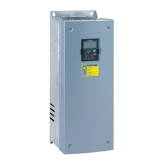
TECHNICAL DATA Introduction Figure 4-1 presents the block diagram of the Vacon NX_ frequency converter. The frequency converter mechanically consists of two units, the Power Unit and the Control Unit. Pictures of the mechanical assemblage on pages 57 to 65. - Page 20 20 • vacon TECHNICAL DATA The control keypad constitutes a link between the user and the frequency converter. The control keypad is used for parameter setting, reading status data and giving control commands. It is detachable and can be operated externally and connected via a cable to the frequency converter. Instead of the control keypad, also a PC can be used to control the frequency converter if connected through a similar cable.
-
Page 21: Power Ratings
NX_ 0300 2 480x1150x362/146 Table 4-1. Power ratings and dimensions of Vacon NX_, supply voltage 208—240V. Note: The rated currents in given ambient temperatures are achieved only when the switching frequency is equal to or less than the factory default. -
Page 22: Vacon Nx_5 - Mains Voltage 380-500 V
1656 FR12 1210x2017x602/600 Table 4-2. Power ratings and dimensions of Vacon NX_, supply voltage 380—500V. Note: The rated currents in given ambient temperatures are achieved only when the switching frequency is equal to or less than the factory default. Note: The rated currents for FR10 to FR12 are valid at an ambient temperature of 40°C (except for 0520 5: rated currents valid at an ambient temperature of 35°C). -
Page 23: Vacon Nx_6 - Mains Voltage 525-690 V
1170 FR12 1210x2017x602/600 Table 4-3. Power ratings and dimensions of Vacon NX_, supply voltage 525—690V. Note: The rated currents in given ambient temperatures are achieved only when the switching frequency is equal to or less than the factory default. Note: The rated currents for FR10 to FR12 are valid at an ambient temperature of 40°C (except for 0416 6, 0590 6 and 0820 6: rated currents valid at an ambient temperature of 35°C). -
Page 24: Brake Resistor Ratings
NX_ 0025 2 NX_ 0261 2 NX_ 0031 2 NX_ 0300 2 NX_ 0048 2 Table 4-4. Brake resistor ratings, Vacon NX_, supply voltage 208–240V Mains voltage 380-500 V, 50/60 Hz, 3~ Max. brake current Resistor nom Max. brake current Resistor nom. - Page 25 NX_ 0750 6 2 x 440 2 x 2.5 NX_ 0100 6 122.2 NX_ 0820 6 2 x 440 2 x 2.5 Table 4-6. Brake resistor ratings, Vacon NX_, supply voltage 525–690V 24-hour support +358 (0)201 212 575 • Email: vacon@vacon.com...
-
Page 26: Technical Data
26 • vacon TECHNICAL DATA Technical data Mains Input voltage U 208…240V; 380…500V; 525…690V; –10%…+10% connection Input frequency 45…66 Hz Connection to mains Once per minute or less Starting delay 2 s (FR4 to FR8); 5 s (FR9) Network imbalance Max. - Page 27 Trips if any of the output phases is missing Overcurrent protection Unit overtemperature protection Motor overload protection Motor stall protection Motor underload protection Short-circuit protection of +24V and +10V reference voltages Table 4-7. Technical data 24-hour support +358 (0)201 212 575 • Email: vacon@vacon.com...
-
Page 28: Installation
Below you will find the dimensions of both wall-mounted as well as flange-mounted Vacon NX_ frequency converters. The dimensions of the opening needed in flange mounting are given in Table 5-3 and Table 5-5. - Page 29 0004—0034 NX_6 0075—0114 NX_2 0072—0105 NX_5 3 x 47 0041—0052 NX_6 0140—0205 NX_2 0140—0205 NX_5 3 x 59 0062—0100 NX_6 Table 5-1. Dimensions for different frequency converter types * = FR5 only 24-hour support +358 (0)201 212 575 • Email: vacon@vacon.com...
- Page 30 30 • vacon INSTALLATION H1 H2 Ø fr5ip21kaulus.fh8 Figure 5-2. Vacon NX_ dimensions, FR4 to FR6; Flange mounting Type Dimensions [mm] ∅ 0004—0012 NX_2 0003—0012 NX_5 0017—0031 NX_2 0016—0031 NX_5 0048—0061 NX_2 0038—0061 NX_5 0004—0034 NX_6 Table 5-2. Dimensions for different frequency converter types FR4 to FR6, flange mounting...
- Page 31 ∅ 0004—0012 NX_2 – – 0003—0012 NX_5 0017—0031 NX_2 – – 0016—0031 NX_5 0048—0061 NX_2 0038—0061 NX_5 0004—0034 NX_6 Table 5-3. Dimensions for the opening for flange mounting, FR4 to FR6 24-hour support +358 (0)201 212 575 • Email: vacon@vacon.com...
- Page 32 32 • vacon INSTALLATION fr7kaulusip21.fh8 Figure 5-4. Vacon NX_ dimensions, FR7 and FR8, flange mounting Type Dimensions [mm] H6 H7 ∅ 0075—0114 NX_2 0072—0105 NX_5 188.5 188.5 23 0041—0052 NX_6 0140—0205 NX_2 0140—0205 NX_5 832* – 0062—0100 NX_6 Table 5-4. Dimensions for different frequency converter types FR7 and FR8, flange mounting *Brake resistor terminal box (202.5 mm) not included, see page 63...
- Page 33 Figure 5-6. The opening needed for the flange mounting, FR8 Type Dimensions [mm] ∅ 0140—0205 NX_2 0140—0205 NX_5 0062—0100 NX_6 Table 5-6. Dimensions for the opening for flange mounting, FR8 24-hour support +358 (0)201 212 575 • Email: vacon@vacon.com...
- Page 34 34 • vacon INSTALLATION Ø fr9ip21.fh8 Figure 5-7. The dimensions Vacon NX_, FR9 Type Dimensions [mm] W1 W2 W3 W4 ∅ 0261—0300 NX_2 0261—0300 NX_5 480 400 165 1120 721 205 16 188 362 340 285 21 1150* 0125—0208 NX_6 Table 5-7.
- Page 35 • 35 Ø Opening fr9collar.fh8 Figure 5-8. Vacon NX_ dimensions. FR9 flange mounting Type Dimensions [mm] ∅ 0261-0300 NX_2 0261-0300 NX_5 1312 1150 0125-0208 NX_6 Table 5-8. Vacon NX_ dimensions. FR9 flange-mounted 24-hour support +358 (0)201 212 575 • Email: vacon@vacon.com...
- Page 36 36 • vacon INSTALLATION Type plate Warning plate Figure 5-9. Vacon NX_ dimensions, FR10 and FR11 (floorstanding units) Type Dimensions [mm] W1 W2 W3 W4 H4 H5 D1 0385…0520 NX_5 595 291 131 15 2018 1900 1435 512 40 602 0261…0416 NX_6...
-
Page 37: Cooling
= min. clearance for fan change = distance from one frequency converter to another or distance to cabinet wall = free space above the frequency converter = free space underneath the frequency converter 24-hour support +358 (0)201 212 575 • Email: vacon@vacon.com... - Page 38 38 • vacon INSTALLATION Type Cooling air required [m 0003—0012 NX_2 0003—0012 NX_5 0017—0031 NX_2 0016—0031 NX_5 0004—0013 NX_6 0048—0061 NX_2 0038—0061 NX_5 0018—0034 NX_6 0075—0114 NX_2 0072—0105 NX_5 0041—0052 NX_6 0140—0205 NX_2 0140—0205 NX_5 0062—0100 NX_6 0261—0300 NX_2 0261—0300 NX_5 1300 0125—0208 NX_6...
-
Page 39: Standalone Units (Fr10 To Fr11)
A = Minimum distance to the side walls or adjacent components. B = Minimum distance from the top of the cabinet C = Free space underneath the module D = Minimum distance between the phase cables 24-hour support +358 (0)201 212 575 • Email: vacon@vacon.com... - Page 40 40 • vacon INSTALLATION Mounting space dimensions [mm] Table 5-12. Mounting space dimensions Type Cooling air required 0385—0520 5 2600 0261—0416 6 0650—0730 5 3900 0460—0590 6 0820—1030 5 5200 0650—0820 6 Table 5-13. Required cooling air Figure 5-11. Cabinet installation space...
-
Page 41: Power Losses
8,00 10,00 12,00 14,00 16,00 Switching frequency [kHz] 0016NX5 400V 0016NX5 500V 0022NX5 400V 0022NX5 500V 0031NX5 400V 0031NX5 500V Figure 5-13. Power loss as function of switching frequency; NX_5 0016…0031 24-hour support +358 (0)201 212 575 • Email: vacon@vacon.com... - Page 42 42 • vacon INSTALLATION 1400,00 1200,00 1000,00 800,00 600,00 400,00 200,00 0,00 0,00 2,00 4,00 6,00 8,00 10,00 12,00 14,00 16,00 Switching frequency [kHz] 0038NX5 400V 0038NX5 500V 0045NX5 400V 0045NX5 500V 0061NX5 400V 0061NX5 500V Figure 5-14. Power loss as function of switching frequency; NX_5 0038…0061...
- Page 43 2000,00 1500,00 1000,00 500,00 0,00 2,00 3,60 6,00 10,00 Switching frequency [kHz] 0261NX5 400V 0261NX5 500V 0300NX 400V 0300NX 500V Figure 5-17. Power loss as function of switching frequency; NX_5 0261…0300 24-hour support +358 (0)201 212 575 • Email: vacon@vacon.com...
- Page 44 44 • vacon INSTALLATION 8000,00 7000,00 6000,00 5000,00 0385NX 400V 0385NX 500V 0460NX 400V 4000,00 0460NX 500V 0520NX 400V 0520NX 500V 3000,00 2000,00 1000,00 0,00 Switching frequency [kHz] Figure 5-18. Power loss as function of switching frequency; NX_5 0385…0520 Tel. +358 (0)201 2121 • Fax +358 (0)201 212 205...
-
Page 45: Cabling And Connections
Recommended fuse types: gG/gL, see Table 6-2 and Table 6-3; If the motor temperature protection of the drive (see Vacon All in One Application Manual) is used as an overload protection, the cable shall be chosen accordingly. If three or more cables are used in parallel for bigger units each cable requires a separate overload protection. -
Page 46: Dc Supply And Brake Resistor Cables
DC supply and brake resistor cables Vacon frequency converters are equipped with terminals for the DC supply and an optional external brake resistor. These terminals are marked with B–, B+/R+ and R–. The DC bus connection is made to terminals B–... -
Page 47: Cable And Fuse Sizes, Nx_6, Fr6 To Fr9
NX0125—NX0144 6 125-144 3*95+50 NX0170 6 95-185 Cu/Al2 5—95 NX0208 6 3*150+70 Table 6-3. Cable and fuse sizes for Vacon NX_6 (FR6 to FR9) based on correction factor 0.7 See chapter 1.4. 24-hour support +358 (0)201 212 575 • Email: vacon@vacon.com... -
Page 48: Cable And Fuse Sizes, Nx_5, Fr10 To Fr11
NX1030 5 1030 630 (6 pcs) Al: 4*(3*300Al+88Cu) Table 6-4. Cable and fuse sizes for Vacon NX_5 (FR10 to FR11) based on correction factor 0.7 6.1.1.7 Cable and fuse sizes, NX_6, FR10 to FR11 The table below shows typical cable sizes and types that can be used with the converter. The final selection should be made according to local regulations, cable installation conditions and cable specification. -
Page 49: Understanding The Power Unit Topology
FR11* Single input Double input* Single output Single output *The FR11 types 0460 6 and 0502 6 have single input terminals nk6_18.fh8 Figure 6-1. Topology of mechanical sizes FR4 – FR11 24-hour support +358 (0)201 212 575 • Email: vacon@vacon.com... -
Page 50: Changing The Emc Protection Class
Changing the EMC protection class The EMC protection level of Vacon NX_ frequency converters can be changed from class H to class T (and from class L to T in NX_6 FR6) with a simple procedure presented in the following figures. - Page 51 Remove screw and capacitor assembly Figure 6-4. Changing of EMC protection class, FR7 FR8 and FR9: Only a Vacon service person may change the EMC protection class of Vacon NXS/P, FR8 and FR9. 24-hour support +358 (0)201 212 575 • Email: vacon@vacon.com...
-
Page 52: Mounting Of Cable Accessories
CABLING AND CONNECTIONS 6.1.4 Mounting of cable accessories Enclosed to your Vacon NXS/P frequency converter you have received a plastic bag containing components that are needed for the installation of the mains and motor cables in the frequency converter. 6.1.4.1 Frames FR4 to FR6 Figure 6-5. -
Page 53: Frames Fr7 And Fr8
5. Place the rubber grommets in the openings as shown in Figure 5. Fix the cable entry gland to the frame of the frequency converter with the five M4x10 screws (Figure 6). Close the cover of the frequency converter. 24-hour support +358 (0)201 212 575 • Email: vacon@vacon.com... - Page 54 54 • vacon CABLING AND CONNECTIONS Tel. +358 (0)201 2121 • Fax +358 (0)201 212 205...
-
Page 55: Installation Instructions
Attach the cable protection plate with the screws. Ensure that the control cables or the cables of the unit are not trapped between the frame and the protection plate. 24-hour support +358 (0)201 212 575 • Email: vacon@vacon.com... -
Page 56: Stripping Lengths Of Motor And Mains Cables
56 • vacon CABLING AND CONNECTIONS 6.1.5.1 Stripping lengths of motor and mains cables Earth Earth conductor conductor MAIN S MOTOR nk6141.fh8 Figure 6-7. Stripping of cables Frame 0140 0168—0205 Table 6-6. Cables stripping lengths [mm] Tel. +358 (0)201 2121 • Fax +358 (0)201 212 205... -
Page 57: Vacon Nx_ Frames And Installation Of Cables
Earth terminals Mains cable Motor cable Figure 6-9. Cable installation in Vacon NXS/P, FR4 NOTE: Two protective conductors are required for FR4 according to standard EN61800-5-1. See page 58 and chapter 1.4. 24-hour support +358 (0)201 212 575 • Email: vacon@vacon.com... - Page 58 58 • vacon CABLING AND CONNECTIONS Figure 6-10. Additional grounding connector for FR4 Tel. +358 (0)201 2121 • Fax +358 (0)201 212 205...
- Page 59 Figure 6-11. Vacon NXS, FR5 (left) NXP (right). Brake resistor DC terminals terminals Earth terminals Mains cable Motor cable Figure 6-12. Cable installation in Vacon NXS/P, FR5 NOTE: See chapter 1.4. 24-hour support +358 (0)201 212 575 • Email: vacon@vacon.com...
- Page 60 60 • vacon CABLING AND CONNECTIONS Figure 6-13. Vacon NXS, FR6 (left), NXP (right). Brake resistor terminals terminals Earth terminals Earth terminals Brake resistor Motor cable terminals Mains cable Motor cable Mains cable Figure 6-14. Cable installation in Vacon NXS/P, FR6 NOTE: See chapter 1.4.
- Page 61 • 61 Figure 6-15. Vacon NXS, FR7 (left), NXP (right). Brake resistor terminals terminals Earth terminals Mains cable Motor cable Figure 6-16. Cable installation in Vacon NXS/P, FR7 NOTE: See chapter 1.4. 24-hour support +358 (0)201 212 575 • Email: vacon@vacon.com...
- Page 62 62 • vacon CABLING AND CONNECTIONS Figure 6-17. Left: Vacon NXS, FR8 (with optional DC/brake resistor connection box on top) Right: Vacon NXP, FR8 (IP54) Tel. +358 (0)201 2121 • Fax +358 (0)201 212 205...
- Page 63 • 63 Motor cable Mains cable Earth terminal Figure 6-18. Cable installation in Vacon NXS/P, FR8 DC terminals Brake resistor terminals Figure 6-19. Brake resistor terminal box on top of FR8 24-hour support +358 (0)201 212 575 • Email: vacon@vacon.com...
- Page 64 64 • vacon CABLING AND CONNECTIONS Figure 6-20. Vacon NXS, FR9 (left), NXP (right) Motor cables Mains cable Earth terminals Figure 6-21. Cable installation in Vacon NXS/P, FR9 Tel. +358 (0)201 2121 • Fax +358 (0)201 212 205...
- Page 65 CABLING AND CONNECTIONS vacon • 65 B– B+/R+ R– Figure 6-22. DC and brake resistor terminals on FR9; DC terminals marked with B– and B+, brake resistor terminals marked with R+ and R– 24-hour support +358 (0)201 212 575 • Email: vacon@vacon.com...
- Page 66 66 • vacon CABLING AND CONNECTIONS Figure 6-23. Example of NXS standalone drives (FR11) Note: More information on cabling for frames FR10 and greater you will find in Vacon NXP/C User’s Manual. Tel. +358 (0)201 2121 • Fax +358 (0)201 212 205...
-
Page 67: Cable Selection And Unit Installation In Accordance With The Ul Standards
NX_5 0168—0205 the terminal screw in order to avoid damage to NX_2 0261—0300 the terminal. NX_5 0261—0300 40/22* NX_6 0125—0208 NX_5 0385—1030 FR10…11 NX_6 0261—820 FR10…11 Table 6-7. Tightening torques of terminals 24-hour support +358 (0)201 212 575 • Email: vacon@vacon.com... -
Page 68: Cable And Motor Insulation Checks
68 • vacon CABLING AND CONNECTIONS 6.1.7 Cable and motor insulation checks 1. Motor cable insulation checks Disconnect the motor cable from terminals U, V and W of the frequency converter and from the motor. Measure the insulation resistance of the motor cable between each phase conductor as well as between each phase conductor and the protective ground conductor. -
Page 69: Control Unit
A and B. On the next pages you will find the arrangement of the control I/O and the relay terminals of the two basic boards, the general wiring diagram and the control signal descriptions. The I/O boards mounted at the factory are indicated in the type code. For more information on the option boards, see Vacon NX option board manual (ud741). -
Page 70: Control Connections
70 • vacon CABLING AND CONNECTIONS 6.2.1 Control connections The basic control connections for boards A1 and A2/A3 are shown in Chapter 6.2.2. The signal descriptions are presented in the All in One Application Manual. +10Vref Reference AI1+ (voltage) AI2+... -
Page 71: Control Cables
See Figure 6-29. The digital inputs are galvanically isolated from the I/O ground. The relay outputs are additionally double- isolated from each other at 300VAC (EN-50178). Figure 6-29. Galvanic isolation barriers 24-hour support +358 (0)201 212 575 • Email: vacon@vacon.com... -
Page 72: Control Terminal Signals
72 • vacon CABLING AND CONNECTIONS 6.2.2 Control terminal signals OPTA1 Terminal Signal Technical information +10 Vref Reference voltage Maximum current 10 mA AI1+ Analogue input, Selection V or mA with jumper block X1 (see page 75): voltage or current Default: 0–... -
Page 73: Digital Input Signal Inversions
Positive logic (+24V is the active signal) = Requires setting of jumper X3 to position the input is active when the switch is closed ‘CMA/CMB isolated from ground’ Figure 6-30. Positive/Negative logic 24-hour support +358 (0)201 212 575 • Email: vacon@vacon.com... -
Page 74: Jumper Selections On The Opta1 Basic Board
74 • vacon CABLING AND CONNECTIONS 6.2.2.2 Jumper selections on the OPTA1 basic board The user is able to customise the functions of the frequency converter to better suit his needs by selecting certain positions for the jumpers on the OPTA1 board. The positions of the jumpers determine the signal type of analogue and digital inputs. - Page 75 AO1 mode: Voltage output; 0...10V = Factory default Figure 6-32. Jumper selection for OPTA1 If you change the AI/AO signal content also remember to change the corresponding board parameter in menu M7. NOTE 24-hour support +358 (0)201 212 575 • Email: vacon@vacon.com...
-
Page 76: Control Keypad
76 • vacon CONTROL KEYPAD CONTROL KEYPAD The control keypad is the link between the Vacon frequency converter and the user. The Vacon NX control keypad features an alphanumeric display with seven indicators for the Run status (RUN, , READY, STOP, ALARM, FAULT) and three indicators for the control place (I/O term/ Keypad/BusComm). -
Page 77: Drive Status Indications
The three text lines (•, ••, •••) provide the user with information on his present location in the keypad menu structure as well as with information related to the operation of the drive. 24-hour support +358 (0)201 212 575 • Email: vacon@vacon.com... - Page 78 78 • vacon CONTROL KEYPAD • = Location indication; displays the symbol and number of menu, parameter etc. Example: M2 = Menu 2 (Parameters); P2.1.3 = Acceleration time •• = Description line; Displays the description of menu, value or fault.
-
Page 79: Keypad Push-Buttons
CONTROL KEYPAD vacon • 79 Keypad push-buttons The Vacon alphanumeric control keypad features 9 push-buttons that are used for the control of the frequency converter (and motor), parameter setting and value monitoring. Figure 7-2. Keypad push-buttons, left: NXS, right: NXP 7.2.1... -
Page 80: Navigation On The Control Keypad
80 • vacon CONTROL KEYPAD Navigation on the control keypad The data on the control keypad are arranged in menus and submenus. The menus are used for example for the display and editing of measurement and control signals, parameter settings (chapter 7.3.2), reference values and fault displays (chapter 7.3.4). -
Page 81: System Menu
Basic parameters Min Frequency Change 13.95 Hz Browse value RU N R EADY READY I/Ote rm I/Oterm Monitor Output frequency No editing! 13.95 Hz Figure 7-3. Keypad navigation chart 24-hour support +358 (0)201 212 575 • Email: vacon@vacon.com... -
Page 82: Monitoring Menu (M1)
82 • vacon CONTROL KEYPAD 7.3.1 Monitoring menu (M1) Menu button right You can enter the Monitoring menu from the Main menu by pushing the when the location indication M1 is visible on the first line of the display. How to browse through the monitored values is presented in Figure 7-4. -
Page 83: Parameter Menu (M2)
Once in the last parameter of a parameter group, you can move directly to the first parameter of that group Browser button up by pushing the See the diagram for parameter value change procedure on page 84. 24-hour support +358 (0)201 212 575 • Email: vacon@vacon.com... - Page 84 84 • vacon CONTROL KEYPAD Ke ypa d Input signals G1G8 READY READY READY Keypad Keypad Keypad Parameters Basic parameters Min Frequency 13.95 Hz READY READY Keypad Keypad Min Frequency Min Frequency 13.95 Hz 14.45 Hz enter Figure 7-5. Parameter value change procedure...
-
Page 85: Keypad Control Menu (M3)
I/Oterm Keypad control Control Place Control Place I/O Remote I/O Remote STOP READY STOP READY I/Oterm Keypad Control Place Control Place enter Keypad Keypad Figure 7-6. Selection of control place 24-hour support +358 (0)201 212 575 • Email: vacon@vacon.com... -
Page 86: Keypad Reference
86 • vacon CONTROL KEYPAD 7.3.3.2 Keypad reference The keypad reference submenu (P3.2) displays and allows the operator to edit the frequency reference. The changes will take place immediately. This reference value will not, however, influence the rotation speed of the motor unless the keypad has been selected as source of reference. -
Page 87: Active Faults Menu (M4)
I/O terminal or fieldbus. Note! Remove external Start signal before resetting the fault to prevent unintentional restart of the drive. READY I/Oterm Normal state, Active faults no faults: 24-hour support +358 (0)201 212 575 • Email: vacon@vacon.com... -
Page 88: Fault Types
88 • vacon CONTROL KEYPAD 7.3.4.1 Fault types In the NX_ frequency converter, there are four different types of faults. These types differ from each other on the basis of the subsequent behaviour of the drive. See Table 7-3. I/Oterm... -
Page 89: Fault Codes
S6 = Reserved S7 = Charging switch S8 = No power to driver card S9 = Power unit communication (TX) S10 = Power unit communication (Trip) S11 = Power unit comm. (Measurement) 24-hour support +358 (0)201 212 575 • Email: vacon@vacon.com... - Page 90 90 • vacon CONTROL KEYPAD Fault Fault Possible cause Correcting measures code Undervoltage DC-link voltage is under the voltage limits In case of temporary supply voltage defined. break reset the fault and restart the − frequency converter. Check the supply...
- Page 91 < 4mA (sel. − control cable is broken or loose signal range 4 − signal source has failed to 20 mA) External fault Digital input fault. Remove fault situation on external device. 24-hour support +358 (0)201 212 575 • Email: vacon@vacon.com...
- Page 92 If installation is correct contact the nearest Vacon distributor. Slot fault Defective option board or slot Check board and slot. Contact the nearest Vacon distributor. PT100 board Temperature limit values set for the Find the cause of temperature rise temp. fault...
-
Page 93: Fault Time Data Record
Real time record If real time is set to run on the frequency converter the data items T1 and T2 will appear as follows: Counted operation days yyyy-mm- Counted operation hours hh:mm:ss, 24-hour support +358 (0)201 212 575 • Email: vacon@vacon.com... -
Page 94: Fault History Menu (M5)
94 • vacon CONTROL KEYPAD 7.3.5 Fault history menu (M5) Fault history menu Main menu Menu button right can be entered from the by pushing the when the location indication M5 is visible on the first line of the keypad display. Find the fault codes in Table 7-4. -
Page 95: System Menu (M6)
Keypad settings P6.6.1 Default page Default page/ P6.6.2 Operating menu P6.6.3 Timeout time 65535 P6.6.4 Contrast P6.6.5 Backlight time Always 65535 S6.7 Hardware settings Internal brake Not connected P6.7.1 Connected resistor Connected 24-hour support +358 (0)201 212 575 • Email: vacon@vacon.com... - Page 96 96 • vacon CONTROL KEYPAD Continuous Temperature P6.7.2 Fan control Continuous First start Calc temp HMI acknowledg. P6.7.3 5000 timeout HMI number of P6.7.4 retries Not connected P6.7.5 Sine filter Connected Connected System S6.8 information S6.8.1 Total counters C6.8.1.1 MWh counter Power On day C6.8.1.2...
-
Page 97: Language Selection
CONTROL KEYPAD vacon • 97 7.3.6.1 Language selection The Vacon control keypad offers you the possibility to control the frequency converter through the keypad in the language of your choice. System menu Menu Locate the language selection page under the . -
Page 98: Copy Parameters
The parameter copy menu (S6.3) embodies four functions: Parameter sets (S6.3.1) The Vacon NX_ frequency converter features a possibility for the user to load back the factory default parameter values and to store and load two customised parameter sets (all parameters included in the application). - Page 99 . Wait until 'OK' appears on the display. The procedure to download the parameters from keypad to drive is similar to that of from drive to keypad. See above. 24-hour support +358 (0)201 212 575 • Email: vacon@vacon.com...
-
Page 100: Parameter Comparison
Browser buttons . Choose with the When the Parameter backup function is activated Vacon NX control keypad makes a copy of the para- meters of the presently used application. Every time a parameter is changed the keypad backup is automatically updated. -
Page 101: Security
Password Password Password Not in use Figure 7-14. Password setting Note! Store the password in a secure location! No changes can be made unless a valid password is entered! 24-hour support +358 (0)201 212 575 • Email: vacon@vacon.com... - Page 102 102 • vacon CONTROL KEYPAD Parameter lock (P6.5.2) This function allows the user to prohibit changes to the parameters. *locked* If the parameter lock is activated the text will appear on the display if you try to edit a parameter value.
-
Page 103: Keypad Settings
CONTROL KEYPAD vacon • 103 Multimonitoring items (P6.5.4) Vacon alpha-numeric keypad features a display where you can monitor even three actual values at the Monitoring values same time (see chapter 7.3.1 and chapter in the manual of the application you are using). -
Page 104: Hardware Settings
104 • vacon CONTROL KEYPAD Default page in the operating menu (P6.6.2) Operating menu Here you can set the location (page) in the (in special applications only) to which the Timeout time display automatically moves as the set (see below) has expired or as the power is switched on to the keypad. - Page 105 Menu button left level with the READY READY READY I/Oterm I/Oterm I/Oterm Fan control Fan control Fan control enter Continuous Temperature Continuous Figure 7-22. Fan control function 24-hour support +358 (0)201 212 575 • Email: vacon@vacon.com...
- Page 106 106 • vacon CONTROL KEYPAD HMI acknowledge timeout (P6.7.3) This function allows the user to change the timeout of the HMI acknowledgement time in cases where there is an additional delay in the RS-232 transmission due to use of modems for communication over longer distances, for example.
-
Page 107: System Info
Trip counters Not reset Not reset STOP READY STOP READY STOP READY Clr Optime cntr Clr Optime cntr Clr Optime cntr enter Reset Reset Not reset Figure 7-24. Counter reset 24-hour support +358 (0)201 212 575 • Email: vacon@vacon.com... - Page 108 108 • vacon CONTROL KEYPAD Software (S6.8.3) Software information page includes information on the following frequency converter software related topics: Page Content 6.8.3.1 Software package 6.8.3.2 System software version 6.8.3.3 Firmware interface 6.8.3.4 System load Table 7-9. Software information pages Applications (S6.8.4)
-
Page 109: Software Version
Expander boards A:NXOPTA1 State Figure 7-26. Expander board information menus Debug menu (S6.8.7) This menu is meant for advanced users and application designers. Contact factory for any assistance needed. 24-hour support +358 (0)201 212 575 • Email: vacon@vacon.com... -
Page 110: Expander Board Menu (M7)
I/Oterm Baud rate Auto Figure 7-27. Expander board information menu Further keypad functions The Vacon NX control keypad embodies additional application-related functions. See Vacon NX Application Package for more information. Tel. +358 (0)201 2121 • Fax +358 (0)201 212 205... -
Page 111: Commissioning
The motor terminals U, V, W and the DC-link/brake resistor terminals –/+ are live when Vacon NX_ is connected to mains, even if the motor is not running. The control I/O-terminals are isolated from the mains potential. How-... - Page 112 112 • vacon COMMISSIONING Set the parameters of group 1 (See Vacon All in One Application Manual) according to the requirements of your application. At least the following parameters should be set: motor nominal voltage motor nominal frequency motor nominal speed motor nominal current You will find the values needed for the parameters on the motor rating plate.
- Page 113 COMMISSIONING vacon • 113 b) Inform your co-workers of the tests. c) Repeat test 8A or 8B. 24-hour support +358 (0)201 212 575 • Email: vacon@vacon.com...
-
Page 114: Fault Tracing
114 • vacon FAULT TRACING FAULT TRACING When a fault is detected by the frequency converter control electronics, the drive is stopped and the symbol F together with the ordinal number of the fault, the fault code and a short fault description appear Reset button on the display. - Page 115 Unbalance Unbalance between power modules in Should the fault re-occur, contact the parallelled units. distributor near to you. Subcode in T.14: S1 = Current unbalance S2 = DC voltage unbalance 24-hour support +358 (0)201 212 575 • Email: vacon@vacon.com...
- Page 116 116 • vacon FAULT TRACING Fault Fault Possible cause Correcting measures code EEPROM Parameter save fault Should the fault re-occur, contact the checksum fault − faulty operation distributor near to you. − component failure Counter fault Values displayed on counters are...
- Page 117 Temperature limit values set for the Find the cause of temperature rise. temp fault PT100 board parameters have been exceeded. More inputs are selected than actually connected. PT100 cable is broken. 24-hour support +358 (0)201 212 575 • Email: vacon@vacon.com...
- Page 118 118 • vacon FAULT TRACING Fault Fault Possible cause Correcting measures code Follower fault When using normal Master Follower function this fault code is given if one or more follower drives trip to fault. Table 9-1. Fault codes Tel. +358 (0)201 2121 • Fax +358 (0)201 212 205...
- Page 120 Find your nearest Vacon service centre Find your nearest Vacon office on the Extranet at: on the Internet at: www.extra.vacon.com www.vacon.com Manual authoring: documentation@vacon.com Document ID: Vacon Plc. Runsorintie 7 65380 Vaasa Finland Subject to change without prior notice © 2011 Vacon Plc.
Need help?
Do you have a question about the nx and is the answer not in the manual?
Questions and answers