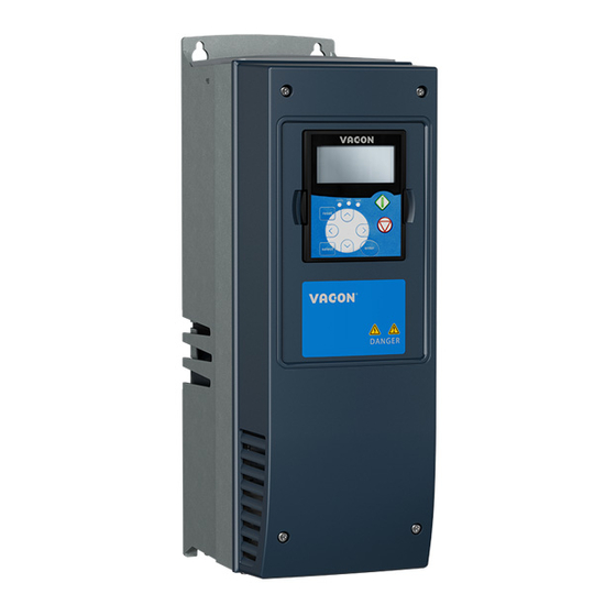
Vacon NX User Manual

Vacon NX User Manual

Ac drives and modbus/tcp option board
Hide thumbs Also See for NX:

Advertisement

vacon nx
ac drives
optci
modbus/tcp option board
user manual

Advertisement

Table of Contents
loading
Need help?

Need help?

Do you have a question about the NX and is the answer not in the manual?

Questions and answers

Subscribe to Our Youtube Channel

Summary of Contents for Vacon NX

  • Page 1 manual...
  • Page 2: Table Of Contents

    LED indications ......................... 4 Ethernet ............................ 5 Connections and Wiring ......................6 Installation ......................... 7 Installing the Ethernet Option Board in a Vacon NX Unit ............7 NCDrive ............................. 9 IP Tool NCIPConfig ........................9 Commissioning ........................ 13 MODBUS/TCP ........................15 Overview ..........................
  • Page 3: Introduction

    Introduction vacon • 3 INTRODUCTION Vacon NX frequency converters can be connected to Ethernet using an Ethernet fieldbus board OPTCI. The OPTCI can be installed in the card slots D or E. Every appliance connected to an Ethernet network has two identifiers; a MAC address and an IP address.
  • Page 4: Ethernet Board Technical Data

    4 • vacon installation ETHERNET BOARD TECHNICAL DATA Overview General Card Name OPTCI Ethernet Interface RJ-45 connector connections Communications Transfer cable Shielded Twisted Pair Speed 10 / 100 Mb Duplex half / full Default IP-address 192.168.0.10 Protocols EtherNet/IP Environment Ambient operating –10°C…50°C...
  • Page 5: Ethernet

    NCDrive / NCIPConfig interface Parameter Slow rate actual Values Trends Fault history Ethernet switch Note! NCDrive can be used in NXS and NXP drives via Ethernet. In NXL drives this is not possible. 24-hour support +358 (0)40 837 1150 • Email: vacon@vacon.com...
  • Page 6: Connections And Wiring

    6 • vacon installation 2. Machine to machine (Industrial environment, fast communication) PLC or Programmable Controller PLC or Programmable Controller PLC or Programmable Controller Master Real - Time Control - Start/Stop, Direction,... - Start/Stop, Direction, .. - Reference - Reference...
  • Page 7: Installation

    Installation vacon • 7 INSTALLATION Installing the Ethernet Option Board in a Vacon NX Unit MAKE SURE THAT THE FREQUENCY CONVERTER IS SWITCHED OFF BEFORE AN OPTION OR FIELDBUS BOARD IS CHANGED OR ADDED! NOTE Vacon NX frequency converter. Remove the cable cover.
  • Page 8 8 • vacon installation Install EtherNet/IP option board in slot D or E on the control board of the frequency converter. Make sure that the grounding plate (see below) fits tightly in the clamp. Make a sufficiently wide opening for your cable by cutting the grid as wide as necessary.
  • Page 9: Ncdrive

    NOTE! NCLoad does not work via Ethernet. See NCDrive help for further information. IP Tool NCIPConfig To begin using the Vacon EtherNet/IP board, you need to set an IP address. The factory default IP address is 192.168.0.10. Before connecting the board to the network, its IP addresses must be set according to the network.
  • Page 10 3.3.1 Update OPTCI Option Board program with the NCIPConfig Tool In some cases it may be necessary to update the option board's firmware. Differing from other Vacon option boards, the EtherNet/IP option board's firmware is updated with the NCIPConfig tool.
  • Page 11 The Safe Mode triggers a fault code (F54). The Board slot error F54 may also appear due to a faulty board, a temporary malfunction of the board or disturbance in the environment. 24-hour support +358 (0)40 837 1150 • Email: vacon@vacon.com...
  • Page 12 12 • vacon installation Configure Option board parameters These features are available from NCIPConfig tool version 1.6. In the tree-view, expand the folders until you reach the board parameters. Slowly double-click the parameter ( Comm. Time-out in figure below) and enter new value. New parameter values are automatically sent to the option board after the modification is complete.
  • Page 13: Commissioning

    Modbus/tcp vacon • 13 COMMISSIONING The Vacon EtherNet/IP board is commissioned with the control keypad by giving values to IP Tool appropriate parameters in menu M7 (or with NCIPConfig tool, read chapter NCIPConfig ). Keypad commissioning is only possible with NXP- and NXS-type frequency converters, not possible with NXL-type frequency converters.
  • Page 14 14 • vacon Commissioning NOTE! If fieldbus cable is broken from Ethernet board end, fieldbus error is generated immediately. All Ethernet parameters are saved to the Ethernet board (not to the control board). If new Ethernet board is changed to control board you must configure the new Ethernet board. Option board parameters are possible to save to the keypad, with NCIPConfig tool or with NCDrive.
  • Page 15: Modbus/Tcp

    Byte 4: Length field, upper byte Byte 5: Length field, lower byte Byte 6: Unit identifier Byte 7: Modbus function code Byte 8: Data (of variable length) Figure 4-1. Modbus Transaction 24-hour support +358 (0)40 837 1150 • Email: vacon@vacon.com...
  • Page 16: Modbus/Tcp Vs. Modbus Rtu

    16 • vacon Commissioning MODBUS/TCP vs. MODBUS RTU Compared to the MODBUS RTU protocol, the MODBUS/TCP differs mostly in error checking and slave addresses. As the TCP already includes an efficient error checking function, the MODBUS/TCP protocol does not include a separate CRC field. In addition to the error checking functionality, the TCP is responsible for resending packets and for splitting long messages so that they fit the TCP frames.
  • Page 17 0x00 Protocol ID 0x00 Length 0x06 Length 0xFF Unit identifier 0x05 Write coil 0x00 Reference number 0x01 Reference number 0xFF Data 0x00 Padding Table 6. Writing a Single Control Word Bit 24-hour support +358 (0)40 837 1150 • Email: vacon@vacon.com...
  • Page 18: Input Discrete

    Both the 'Coil register' and the 'Input discrete register' contain binary data. However, the difference between the two registers is that the Input register's data can only be read. The Vacon Ethernet board's MODBUS/TCP implementation uses the following Input discrete addresses.
  • Page 19 Transaction ID 0x00 Protocol ID 0x00 Protocol ID 0x00 Length 0x04 Length 0xFF Unit identifier 0x02 Read input discretes 0x01 Byte count 0x41 Data Table 11. Status Word Read - Response 24-hour support +358 (0)40 837 1150 • Email: vacon@vacon.com...
  • Page 20: Holding Registers

    20 • vacon Commissioning In the responses' data field, you can read the bit mask (0x41) that corresponds to the read discrete status after shifting with the 'Reference number' field value (0x00, 0x00). LSB 0x1 MSB 0x4 Table 12. Response's Data Block Broken into Bits In this example, the frequency converter is in the 'ready' mode because the first 0 bit is set.
  • Page 21 If the IDMap table has not been initialized, all fields show the index '0'. If the IDMap has been initialized, the parameter ID's included in it are stored in the OPTCI board's FLASH memory. 24-hour support +358 (0)40 837 1150 • Email: vacon@vacon.com...
  • Page 22 22 • vacon Commissioning 5.7.3 FB Process Data Out (Read) The 'Process data out' registers are mainly used for controlling frequency converters. You can read temporary values, such as frequency, voltage and moment, using the process data. The table values are updated every 10ms.
  • Page 23 Fieldbus Din 8 ON Fieldbus Din 9 OFF Fieldbus Din 9 ON Fieldbus Din 10 OFF Fieldbus Din 10 ON Not in use Not in use Table 19. Control Word bit description 24-hour support +358 (0)40 837 1150 • Email: vacon@vacon.com...
  • Page 24: Input Registers

    24 • vacon Commissioning 5.7.5 Measurement Table The measurement table provides 25 readable values as listed in the following table. The table values are updated every 100ms. Read restrictions, possible to read 25 consecutive ID address. Address Purpose Type 10301...
  • Page 25 The fault history can contain 29 faults at any time. The fault history contents are represented as follows. Fault code Sub-code Value as a hexadecimal Value as a hexadecimal Table 25. Fault Coding 24-hour support +358 (0)40 837 1150 • Email: vacon@vacon.com...
  • Page 26 26 • vacon Commissioning For example, the IGBT temperature fault code 41, sub-code 00: 2900Hex -> 4100Dec. For complete list of fault codes please see frequency converter’s manual Note! It is very slow to read whole fault history (30401-30430) at a time. It is recommended to read only parts of the fault history at a time.
  • Page 27: Start-Up Test

    Frequency Converter Settings Select fieldbus as the active control bus. (For more information see the Vacon NX User´s Manual, section 7.3.3). Master Unit Programming 1. Write a FB 'Control Word' (address: 42001) of value 1Hex 2.
  • Page 28: Error Codes And Errors

    28 • vacon Error Codes and Errors ERROR CODES AND ERRORS Frequency Converter Error Codes To make sure that the board functions are correctly in all circumstances and that no errors occur, the board set the fieldbus error 53 if it doesn't have a functional connection to the Ethernet network or if the connection is faulty.
  • Page 29: Appendix

    Process Data. The monitor- ing values and drive parameters can be selected using the ID number (see NX All in One Application Manual, Tables for monitoring values and parameters). Default selections are as in the table above.
  • Page 30 30 • vacon Appendix PID control and Pump and fan control applications Data Value Unit Scale 2003 Reference Speed Reference 0.01% 2001 ControlWord Start/Stop Command Fault reset Command 2004 Process Data IN1 Reference for PID 0.01% controller 2005 Process Data IN2 Actual Value 1 to PID 0.01%...
  • Page 32 Find your nearest Vacon service centre Find your nearest Vacon office on the Extranet at: on the Internet at: www.extra.vacon.com www.vacon.com Manual authoring: documentation@vacon.com Document ID: Vacon Plc. Runsorintie 7 65380 Vaasa Finland Subject to change without prior notice © 2012 Vacon Plc.

This manual is also suitable for:

Optci

Table of Contents

Save PDF