Sign In
Upload
Manuals
Brands
Vacon Manuals
Media Converter
nxs
Vacon nxs Manuals
Manuals and User Guides for Vacon nxs. We have
3
Vacon nxs manuals available for free PDF download: User Manual, Manual
Vacon nxs User Manual (165 pages)
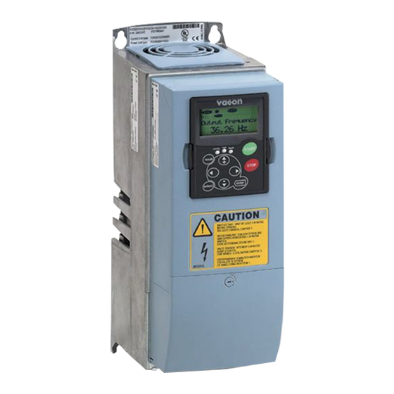
wall-mounted drives standalone drives
Brand:
Vacon
| Category:
Controller
| Size: 2 MB
Table of Contents
11 Appendix
1
About this Manual
3
Start-Up Quick Guide
4
Table of Contents
5
1 Approvals
8
2 Safety
12
The Safety Symbols Used in the Manual
12
Warning
12
Caution
13
Grounding and Earth Fault Protection
14
Electro-Magnetic Compatibility (EMC)
15
Using an RCD or an RCM Device
15
3 Receiving the Delivery
17
Package Label
17
Type Designation Code
18
Storage
21
Removing the Packaging and Lifting the AC Drive
21
Weight of the AC Drive
21
Accessories
22
FR4-FR6 Cable Accessories
22
FR7-FR8 Cable Accessories
24
Product Modified" Label
27
Disposal
27
4 Mounting
28
General Information about Mounting
28
Dimensions for Wall Mounting
29
Wall Mounting of FR4-FR6
29
Wall Mounting of FR7
30
Wall Mounting of FR8
31
Wall Mounting of FR9
32
Dimensions for Flange Mounting
33
Flange Mounting of FR4 to FR6
33
Flange Mounting of FR7 and FR8
35
Flange Mounting of FR9
38
Dimensions for Standalone
39
Standalone (FR10 and FR11)
39
Cooling
40
Cooling of FR4 to FR9
40
Cooling of Standalone AC Drives (FR10 to FR11)
43
5 Power Cabling
44
Cable Connections
44
UL Standards on Cabling
46
Cable Dimensioning and Selection
46
Cable and Fuse Sizes for 208-240 V and 380-500 V, FR4 to FR9
47
Cable and Fuse Sizes for 500-690 V, FR6 to FR9
51
Cable and Fuse Sizes for 380-500 V, FR10 to FR11
53
Cable and Fuse Sizes for 500-690 V, FR10 to FR11
55
Understanding the Power Unit Topology
56
Brake Resistor Cables
57
Preparing for the Cable Installation
58
Cable Installation
58
Frames FR4 to FR7
58
Frames FR8 to FR9
64
Frames FR10-FR11
69
6 Control Unit
70
Control Unit Components
70
Control Unit Cabling
71
Selection of the Control Cables
71
Control Terminals
71
Installation of Option Boards
75
Galvanic Isolation Barriers
76
7 Control Panel
77
Control Keypad
77
Display
78
Navigation on the Control Panel
79
Using the Monitoring Menu (M1)
81
Using the Parameter Menu (M2)
82
Finding the Parameter
82
Editing the Text Values
83
Editing the Numerical Values
84
Using the Keypad Control Menu (M3)
85
Control Place
85
The Keypad Reference Submenu (P3.2)
86
Changing the Rotation Direction
87
Disabling the Stop Motor Function
87
Special Functions in the Keypad Control Menu
87
Using the Active Faults Menu (M4)
88
The Fault Time Data Record
88
Using the Fault History Menu (M5)
90
Resetting the Fault History Menu
91
Using the System Menu (M6)
91
Changing the Language
95
Changing the Application
95
Copy Parameters (S6.3)
96
Comparing the Parameters
99
Security
101
Keypad Settings
105
Hardware Settings
107
System Info
112
Using the Expander Board Menu (M7)
117
Examining the Connected Expander Boards
118
Finding the Expander Board Parameters
119
Further Keypad Functions
120
8 Commissioning and Additional Instructions
121
Commissioning Safety
121
Commissioning of the Drive
122
Operation of the Motor
122
Checks before Starting the Motor
122
The Run Test Without the Motor
123
Start-Up Test
123
Identification Run
123
Connecting the Motor to the Process
123
Measuring the Cable and Motor Insulation
124
Installation in an IT System
124
Frames FR4, FR5, and FR6
124
Frame FR7
125
Frames FR8 - FR11
127
Maintenance
127
Capacitor Reforming
128
9 Technical Data for NXS and NXP
129
AC Drive Power Ratings
129
Mains Voltage 208-240 V
129
Mains Voltage 380-500 V
131
Mains Voltage 500-690 V
133
Overload Capability
135
Brake Resistor Ratings
136
Vacon ® NXS and NXP - Technical Data
140
The Compliance with the Product Standard IEC/EN 61800-3 + A1
145
Environment Definitions in Product Standard IEC/EN 61800-3 + A1
147
10 Fault Tracing
148
Resetting a Fault
148
Fault Codes
150
Power Losses for 380-500 V
157
Appendix 1
157
Power Losses of 500-690 V
162
Advertisement
Vacon nxs User Manual (120 pages)
Frequency Converter
Brand:
Vacon
| Category:
Media Converter
| Size: 3 MB
Table of Contents
Table of Contents
3
Vacon
3
Safety
8
Danger
8
Warnings
8
Cautions
9
Earthing and Earth Fault Protection
9
Running the Motor
10
Eu Directive
11
CE Marking
11
EMC Directive
11
General
11
Technical Criteria
11
Vacon Frequency Converter EMC Classification
11
Environment Definitions in Product Standard en 61800-3 (2004)
12
Manufacturer's Declaration of Conformity
12
Receipt of Delivery
16
Type Designation Code
16
Storage
17
Maintenance
17
Capacitor Recharge
17
Warranty
18
Technical Data
19
Introduction
19
Power Ratings
21
Vacon NX_2 - Mains Voltage 208-240 V
21
Vacon NX_5 - Mains Voltage 380-500 V
22
Vacon NX_6 - Mains Voltage 525-690 V
23
Brake Resistor Ratings
24
Technical Data
26
Installation
28
Mounting
28
Cooling
37
FR4 to FR9
37
Standalone Units (FR10 to FR11)
39
Power Losses
41
Power Losses as Function of Switching Frequency
41
Cabling and Connections
45
Power Unit
45
Power Connections
45
Mains and Motor Cables
45
DC Supply and Brake Resistor Cables
46
Control Cable
46
Cable and Fuse Sizes, NX_2 and NX_5, FR4 to FR9
46
Cable and Fuse Sizes, NX_6, FR6 to FR9
47
Cable and Fuse Sizes, NX_5, FR10 to FR11
48
Cable and Fuse Sizes, NX_6, FR10 to FR11
48
Understanding the Power Unit Topology
49
Changing the EMC Protection Class
50
Mounting of Cable Accessories
52
Frames FR4 to FR6
52
Frames FR7 and FR8
53
Mounting Procedure
53
Installation Instructions
55
Stripping Lengths of Motor and Mains Cables
56
Vacon NX_ Frames and Installation of Cables
57
Cable Selection and Unit Installation in Accordance with the UL Standards
67
Cable and Motor Insulation Checks
68
Control Unit
69
Control Connections
70
Control Cables
71
Galvanic Isolation Barriers
71
Control Terminal Signals
72
Digital Input Signal Inversions
73
Jumper Selections on the OPTA1 Basic Board
74
Control Keypad
76
Indications on the Keypad Display
76
Control Place Indications
77
Drive Status Indications
77
Status Leds (Green - Green - Red)
77
Text Lines
77
Button Descriptions
79
Keypad Push-Buttons
79
Navigation on the Control Keypad
80
System Menu
81
Monitoring Menu (M1)
82
Parameter Menu (M2)
83
Keypad Control Menu (M3)
85
Selection of Control Place
85
Keypad Direction
86
Keypad Reference
86
Stop Button Activated
86
Active Faults Menu (M4)
87
Fault Types
88
Fault Codes
89
Fault Time Data Record
93
Fault History Menu (M5)
94
System Menu (M6)
95
Application Selection
97
Language Selection
97
Copy Parameters
98
Parameter Comparison
100
Security
101
Keypad Settings
103
Hardware Settings
104
System Info
107
Software Version
109
Expander Board Menu (M7)
110
Further Keypad Functions
110
Commissioning
111
Fault Tracing
114
Vacon nxs Manual (55 pages)
Frequency converters
Brand:
Vacon
| Category:
Media Converter
| Size: 0 MB
Table of Contents
Table of Contents
2
Index
2
1 General
3
Heat Exchanger Application
3
2 Control I/O
4
3 Parameter Lists
5
Monitoring Values (Control Keypad: Menu M1)
5
FB Monitor
6
Status Word, ID43
6
Status Word 2, ID1800
6
Fault Word 1, ID1172
7
Fault Word 2, ID1173
7
Warning Word 1, ID1174
7
Fault Word 10, ID1202
8
Warning Word 10, ID1269
8
Basic Parameters (Control Keypad: Menu M2 G2.1)
9
Input Signals (Control Keypad: Menu M2 G2.2)
10
Output Signals (Control Keypad: Menu M2 G2.3)
11
Analogue Output 1
11
Analogue Output 2
11
Analogue Output 3
12
Relay Output 1
12
Relay Output 2
13
Relay Output 3
13
Relay Output 4
13
Relay Output 5
14
Relay Output 6
14
Drive Control Parameters (Control Keypad: Menu M2 G2.4)
15
Prohibit Frequency Parameters (Control Keypad: Menu M2 G2.5)
15
Motor Control Parameters (Control Keypad: Menu M2 G2.6)
16
Protections (Control Keypad: Menu M2 G2.7)
17
PID Control Parameters (Control Keypad: Menu M2 G2.9)
18
Flow Control Parameters (Control Keypad: Menu M2 G2.10)
19
Fieldbus Parameters (Control Keypad: Menu M2 G2.11)
20
Keypad Control (Control Keypad: Menu M3)
21
System Menu (Control Keypad: M6)
21
Expander Boards (Control Keypad: Menu M7)
21
4 Description of Parameters
22
Current Limit
22
Minimum/Maximum Frequency
22
U/F Ratio Selection
22
Linear and Squared Change of Motor Voltage
23
Programmable U/F Curve
23
U/F Optimisation
23
Nominal Speed and Current of Motor
24
Nominal Voltage and Frequency of Motor
24
Parameter Conceal
24
I/O Frequency Reference Selection
25
Keypad/Fieldbus Frequency Reference Selection
25
PID Controller Gain
25
PID Controller I-Time
25
PID Controller Function as I-Controller
26
PID Activation
27
PID Output Curve with the Values of Example 2
27
PID Output with the Values of Example 3
27
Analogue Output 1 Function
28
DIN3 as DC-Brake Command Input
28
DIN3 Function
28
Analogue Output 1 Filter Time
29
Analogue Output 1 Inversion
29
Analogue Output 1 Minimum
29
Analogue Output 1 Scale
29
Output Frequency Limit Supervision Function
30
Output Frequency Limit Supervision Value
30
Output Signals Via Relay Outputs RO1 and RO2
30
Relay Output 1 Function
30
Actual Value 1 Minimum and Maximum Scale
31
Actual Value Selection
31
Example of Actual Value Signal Scaling
31
PID Controller Reference Signal
31
AI1 Custom Setting Minimum Maximum
32
AI1 Signal Filter Time
32
AI1 Signal Range
32
PID Error Value Inversion
32
AI1 Signal Inversion
33
AI2 Signal Filter Time
33
AI2 Signal Range
33
AI2 Custom Setting Minimum/Maximum
34
AI2 Signal Inversion
34
Acceleration/Deceleration Ramp 1 Shape
35
Brake Chopper
35
Start Function
35
DC-Braking Current
36
DC-Braking Time at Stop
36
Stop Function
36
Prohibit Frequency Area 1; Low and High Limit
37
Acceleration/Deceleration Ramp Speed Scaling Ratio between Prohibit Frequency Limits 23457
38
DC-Braking Frequency at Stop and Start
38
Flux Brake
38
Flux Braking Current
38
Motor Control Mode
39
Switching Frequency
39
U/F Curve, Middle Point Frequency and Voltage
39
Voltage at Field Weakening Point
39
Overvoltage Controller
40
Undervoltage Controller
40
Earth Fault Protection
41
Output Phase Supervision
41
Response to External Fault
41
Response to the 4Ma Reference Fault
41
Motor Thermal Protection: Motor Ambient Temp. Factor
42
Motor Thermal Protection: Motor Duty Cycle
42
Motor Thermal Protection: Time Constant
42
Motor Temperature Calculation
43
Stall Characteristics Settings
43
Stall Current Limit
43
Stall Protection
43
Stall Frequency Limit
44
Stall Time
44
Underload Protection
44
Underload Protection, Field Weakening Area Load
44
Automatic Restart: Trial Time
45
Automatic Restart: Wait Time
45
Underload Protection, Zero Frequency Load
45
Underload Time
45
Automatic Restart
46
Automatic Restart: Start Function
46
Input Phase Supervision
46
Response to Undervoltage Fault
46
Actual Value Supervision Delay
47
Actual Value Supervision Function
47
Actual Value Supervision Limit
47
Response to Fieldbus and Slot Fault
47
Fieldbus Data out Selections 1 to 8
48
Some Typical Values
48
Constant Speed
49
Coolant Inlet Pressure, Minimum and Maximum
49
Delayed Fault
49
Relay Output 3 Function
49
AI3 Signal Selection
51
Coolant Inlet Pressure Alarm Limit
51
Coolant Inlet Pressure Supervision
51
DIN2 Input
51
Autochange Interval
52
Control Place
53
Keypad Control Parameters
53
Keypad Direction
53
Stop Button Activated
53
Advertisement
Advertisement
Related Products
Vacon nxsp
Vacon NXP/C 5 Series
Vacon NX_0261 5
Vacon NX_0590 5
Vacon NX_0820 5
Vacon NX_0261 6
Vacon NX_1180 6
Vacon NX_1030 6
Vacon NX_0820 6
Vacon NX_0125 6
Vacon Categories
Controller
Media Converter
DC Drives
Inverter
Power Supply
More Vacon Manuals
Login
Sign In
OR
Sign in with Facebook
Sign in with Google
Upload manual
Upload from disk
Upload from URL