Table of Contents
Advertisement
Quick Links
Advertisement
Table of Contents

Related Manuals for Vacon OPTC4


Summary of Contents for Vacon OPTC4
- Page 1 manual...
-
Page 2: Table Of Contents
3.2 Grounding of bus cable shield in OPT-C4 ..................8 3.3 Bus termination resistors ......................10 3.4 LED indications ........................... 10 INSTALLATION OF VACON NX LonWorks BOARD ............. 12 4.1 Board information sticker ......................14 COMMISSIONING ......................15 5.1 Fieldbus board parameters ......................15 5.2 Start-up test .......................... -
Page 3: General
GENERAL Vacon NX frequency converters can be connected to the LonWorks® network using a fieldbus board. The converter can then be controlled, monitored and programmed from the Host system. The LonWorks® board shall be installed in slot E on the control board of the frequency converter. -
Page 4: Lonworks Option Board Technical Data
4 • vacon technical data LONWORKS OPTION BOARD TECHNICAL DATA General LonWorks Interface Pluggable connector (5 mm) connections Communications Channel type TP/FT-10 Transfer cable Twisted pair Baud rate 78 Kbit/s Environment Ambient operating –10°C…50°C temperature Storing –40°C…70°C temperature Humidity <95%, no condensation allowed Altitude Max. -
Page 5: Physical Media And Wiring
• 5 Physical media and wiring networks can be implemented on many different physical media. Vacon OPT- ORKS C4 option board is equipped with an FT-X1 transceiver supporting the Free Topology transformer coupled network, which allows the network wire to be connected as bus, star, loop or combination of these. -
Page 6: Profiles
6 • vacon technical data converters. Attention should be paid to proper grounding of the shield to ensure bus operation. Grounding of the shield should be done at both ends of the cable. Max. doubly Max. free Max. node-to-node Cable type... -
Page 7: Lonworks Fieldbus Board Layout And Connections
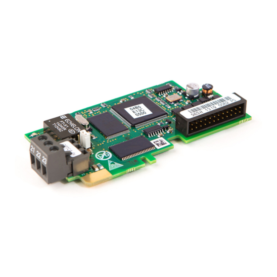
• 7 LONWORKS FIELDBUS BOARD LAYOUT AND CONNECTIONS Vacon LonWorks Fieldbus Board is connected to the fieldbus through 3-pin pluggable bus connector. The communication with the control board takes place through the standard Vacon Interface Board Connector. -
Page 8: Grounding Of Bus Cable Shield In Opt-C4
8 • vacon layout and connections Grounding of bus cable shield in OPT-C4 The bus cable shield can be grounded to the frame of the frequency converter through an RC filter located on the OPT-C4 board. Note: Normally, the option board has already been installed in slot E of the control board. It is not necessary to detach the whole board for the grounding of the bus cable shield. - Page 9 • 9 Figure 3-4. Insert the data cables and the shield in their respective terminals. See Table 3-1. Figure 3-5. If the LonWorks board was detached from the control unit place it into slot E of the control board (see board installation on page 12).
-
Page 10: Bus Termination Resistors
Free topology network segment requires only one termination whereas a doubly terminated bus topology requires two. The jumper X5 on the Vacon LonWorks board must be set accordingly. Use 94-ohm termination resistance when only one termination is needed and 47-ohm for two terminations. - Page 11 • 11 Neuron status (H3) GREEN LED is: Meaning: State Code Configured Applicationless and Unconfigured Flashing Unconfigured Board status LED (H2) YELLOW LED is: Meaning: Option board not activated Option board in initialisation state waiting for activation command from the...
-
Page 12: Installation Of Vacon Nx Lonworks Board
12 • vacon installation INSTALLATION OF VACON NX LONWORKS BOARD MAKE SURE THAT THE FREQUENCY CONVERTER IS SWITCHED OFF BEFORE AN OPTION OR FIELDBUS BOARD IS CHANGED OR ADDED! NOTE Vacon NX frequency converter Remove the cable cover. Open the cover of the control unit. - Page 13 • 13 Install LonWorks option board in slot E on the control board of the frequency converter. Make sure that the grounding plate (see below) fits tightly in the clamp. lw1.fh8 Make a sufficiently wide opening for your cable by cutting the grid as wide as necessary.
-
Page 14: Board Information Sticker
14 • vacon installation Board information sticker The LonWorks option board package delivered by the factory includes a sticker (shown below). Please mark the board type (1), the slot into which the board is mounted (2) and the mounting date (3) on the sticker. -
Page 15: Commissioning
READ FIRST CHAPTER 8 'COMMISSIONING' IN VACON NX USER'S MANUAL (Document nr. ud00701, please visit http://www.vacon.com/support/documents.html). Fieldbus board parameters The Vacon LonWorks board is commissioned with the control keypad by giving values to appropriate parameters in menu M7 (for locating the expander board menu, see Vacon NX User's Manual, Chapter 7). -
Page 16: Start-Up Test
16 • vacon commissioning Start-up test Frequency converter application (Bus/Comm) Choose Fieldbus for the active control place (see Vacon NX User's Manual, Chapter 7.3.3). Master software nviDrvSpeedStpt 1. Write 100.0 1 to nviDrvSpeedScale 2. Frequency converter status is RUN and output frequency is 1.00 * nviDrvSpeedStpt 3. -
Page 17: Lonworks Interface
LONWORKS INTERFACE Features of the LonWorks interface: • Direct control of Vacon NX (e.g. Run, Stop, Direction, Speed reference, Fault reset) • Full access to all Vacon NX parameters • Monitor Vacon NX status (e.g. Output frequency, Output current, Fault code) - Page 18 18 • vacon lonworks interface Variable Speed Motor Drive: 6010 Mandatory nviDrvSpeedStpt nvoDrvSpeed Network SNVT_switch SNVT_levPercent Variables nvoDrvCurnt Optional SNVT_amp nviDrvSpeedScale nvoDrvPwr Network SNVT_lev_percent SNVT_power_kilo nvoDrvRunHours Variables SNVT_time_hour Configuration Properties nc50 nciMaxSpeed nc53 nciMinSpeed nc48 nciRcvHrtBt nc49 nciSndHrtBt nc52 nciMinOutTm...
-
Page 19: Input Network Variables
• 19 Input Network Variables Function Variable Name SNVT type Min. Max. Value Value Node Object request nviRequest SNVT_obj_request Driver speed setpoint nviDrvSpeedStpt SNVT_switch Driver set point speed nviDrvSpeedScale SNVT_lev_percent -163.840% 163.830% scaling Reset fault nviRstFault SNVT_switch... - Page 20 20 • vacon lonworks interface nviRstFault This input network variable provides a fault reset. Setting value 1 for State and a non-zero value for Value will reset an active fault in Vacon NX. Default value is 0; 0. State Value Command no action (0;...
- Page 21 • 21 nviParCmd This input network variable is used to read and write the parameters. The parameter addresses are determined in the application. Every parameter and actual value has been given an ID number in the application. The ID numbering of the parameter as well as the parameter ranges and steps can be found in the application manual in question.
-
Page 22: Output Network Variables
22 • vacon lonworks interface If the read command is successful then nvoParOut value is - LN_RECALL 112 <0 0 5 A0> 0 0 0 0 If the read command fails then nvoParOut value is - LN_ LN_NUL 112 <0 0 0 0> 0 0 0 0... - Page 23 In such cases the real value can be seen on Vacon NX’s operating keypad. nvoActFault This output network variable provides the drive active fault code. If the value is 0 the frequency converter has no fault. See the fault code list in Vacon NX Frequency Converter User’s Manual for fault identification. nvoProcessOut1..8 These output network variables are sent directly from the application (see more detailed explanation in chapter 6.5 Process data) The valid range is 0 to 65535 (-163,840 to 163,835).
- Page 24 24 • vacon lonworks interface nvoDigitalOut1..8 These output network variables are sent directly from the application (see more detailed explanation in chapter 6.5 Process data). state value command off (0; 0) 200 (0xC8) on (200; 1) -1 (0XfF) invalid (NULL) Table 6-9.
-
Page 25: Network Configuration Variables
• 25 Network Configuration Variables Function Variable Name SNVT type Maximum motor speed nciMaxSpeed SCPTmaxSetpoint Minimum motor speed nciMinSpeed SCPTminSetpoint Receive heartbeat time nciRcvHrtBt SCPTmaxRcvTime Send heartbeat time nciSndHrtBt SCPTmaxSndTime Minimum output time nciMinOutTime SCPTminSndTime Nominal motor speed in RPM... - Page 26 This configuration property is used to provide the nominal frequency for the motor. nciRampUpTm Defines the acceleration time for Vacon NX. The valid range is 0.0 to 6,553.4 sec (0.1 sec). nciRampDownTm Defines the deceleration time for Vacon NX. The valid range is 0.0 to 6,553.4 sec (0.1 sec).
-
Page 27: Process Data
• 27 Process data Aplication FBProcessDataIn1..8 nviProcessIn1..8 nviDigitaln 1 bit 3 FBFixedControlWord bit 4 nviDigitaln 2 bit 5 nviDigitaln 3 bit 6 nviDigitaln 4 nviDigitaln 5 bit 7 nviDigitaln 6 bit 10 bit 11 nviDigitaln 7 bit 12 nviDigitaln 8 nvoProcessOut1..8... -
Page 28: Fault Tracking
FAULT TRACKING The table below presents the faults related to the LonWorks option board. For more information, see also Vacon NX User's Manual, Chapter 9. The LonWorks option board status LEDs are described in more detail in Chapter 3.4. Fault... - Page 29 • 29 APPENDIX 1 Process Data OUT The nodes can read the frequency converter’s actual values using process data variables. Basic, Standard, Local/Remote, Multi-Step, PID control and Pump and fan control applications use process data as follows: Data...
- Page 30 30 • vacon appendix PID control and Pump and fan control applications Data Value Unit Step Process Data IN1 Reference for PID 0.01% controller Process Data IN2 Actual Value 1 to PID 0.01% controller Process Data IN3 Actual Value 2 to PID 0.01%...
- Page 32 Find your nearest Vacon service centre Find your nearest Vacon office on the Extranet at: on the Internet at: www.extra.vacon.com www.vacon.com Manual authoring: documentation@vacon.com Document ID: Vacon Plc. Runsorintie 7 65380 Vaasa Finland Subject to change without prior notice © 2012 Vacon Plc.
Need help?
Do you have a question about the OPTC4 and is the answer not in the manual?
Questions and answers