Key Automation CT102 24 Instructions And Warnings For Installation And Use
Control unit for a 24 vdc motor, for a sliding gate, up-and-over door or barrier
Hide thumbs
Also See for CT102 24:
- Quick start manual (16 pages) ,
- Instructions and warnings for installation and use (108 pages)
Advertisement
Centrale per un motore 24 Vdc, per cancello scorrevole, portone basculante o barriera
Control unit for a 24 Vdc motor, for a sliding gate, up-and-over door or barrier
Logique de commande pour un moteur 24 Vdc, pour portail coulissant, porte basculante ou barrieres
Central para un motor 24 Vdc, para puerta de corredera, portón basculante o barreras
Steuergerät für einen Motor 24 Vdc, für Schiebetor, Schwingtor oder Schrankenöffnung
Unidade para um motor 24 Vdc, para portão de correr, portão basculante ou barreira
Centrala do silnika 24 Vdc, napędzającego przesuwną bramę ogrodzeniową,
Istruzioni ed avvertenze per l'installazione e l'uso
Instructions and warnings for installation and use
Instructions et avertissements pour l'installation et l'usage
Instrucciones y advertencias para su instalación y uso
Anleitungen und Hinweise zu Installation und Einsatz
Instruções e advertências para a instalação e utilização
CT102 24
Management
System
ISO 9001:2008
www.tuv.com
ID 9105043769
uchylną bramę garażową lub szlaban
Advertisement

Related Manuals for Key Automation CT102 24


Summary of Contents for Key Automation CT102 24
- Page 1 Anleitungen und Hinweise zu Installation und Einsatz Instruções e advertências para a instalação e utilização CT102 24 Centrale per un motore 24 Vdc, per cancello scorrevole, portone basculante o barriera Control unit for a 24 Vdc motor, for a sliding gate, up-and-over door or barrier Logique de commande pour un moteur 24 Vdc, pour portail coulissant, porte basculante ou barrieres Central para un motor 24 Vdc, para puerta de corredera, portón basculante o barreras...
-
Page 2: Table Of Contents
TABLE OF CONTENTS Safety warnings pag. 17 Introduzione al prodotto pag. 18 Descrizione della centrale pag. 18 Descrizione dei collegamenti pag. 18 Modelli e caratteristiche tecniche pag. 18 Elenco cavi necessari pag. 19 Preliminary Checks pag. 19 Installing the Product pag. - Page 3 Read the instructions carefully before proceeding with installation. should this occur, disconnect the power supply immediately and contact a Key Automation Service Centre. Use of the automation The design and manufacture of the devices making up the system in these conditions may cause hazards;...
- Page 4 Key Automation motors for the electric opening and closure working times and operating modes. of sliding gates, up-and-over doors and electromechanical barrier.
- Page 5 - Power supply with protection against short-circuits inside the con- - Safety device deactivation by means of dip switches: there is no trol unit, on motors and on the connected accessories. need to bridge the terminals of safety devices which are not instal- - Obstacle detection.
-
Page 6: Electrical Connections
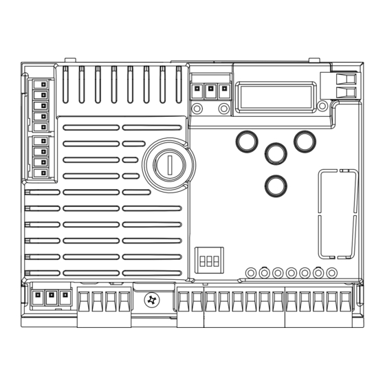
4 - PRODUCT INSTALLATION 4.1 - Electrical connections WARNING - Before making the connections, ensure that the control unit is not powered up. POWER SUPPLY CONNECTOR MOTOR CONNECTOR Power supply live 230 Vac (120 Vac) 50-60 Hz Power supply connection terminal board Power supply neutral 230 Vac (120 Vac) 50-60 Hz Power supply motor Earth... -
Page 7: Display During Normal Operation
SAFETY AND CONTROL DEVICE CONNECTOR Common for the FLASH-IND-LED inputs FLASH Flashing light output 24Vdc (without regulation), maximum 25W IND output for gate open indicator light 24 Vdc not regulated 4W MAX / Electric lock output 12Vac, 15VA maximum IN.D. selectable with parameter Courtesy light output 24Vdc (without regulation), maximum 25W, controllable also via radio ON-OFF command (radio channel 4) - Page 8 KEY TO MAIN CONTROL EVENT DESCRIPTION FLASHING LIGHT AND KEY LEDS CONTROL UNIT Gate opening opening Gate closing closure Gate open with timed reclosure active automatic closure Gate stopped during closure stop during closure Gate stopped during opening stop during opening Gate completely open without automatic reclosure open Gate completely closed...
-
Page 9: Autolearning Of The Travel Stroke
4.3 - Autolearning of the travel stroke The irst time the control unit is powered up, an autolearning proce- as the travel stroke length and deceleration points. dure must be carried out to acquire fundamental parameters such AUTOLEARNING OF THE TRAVEL STROKE AND MAIN PARAMETERS The decelerations will be those set in the menu, with the same percentage during both opening and closing. -
Page 10: Customising The System - Basic Menu
DELETING A TRANSMITTER 1. Exit the programming menus by pressing MENU. CS.r. ” (Clear single Remote) appears on display. 2. Press and hold “DOWN” until the text “ 3. Release the button. At this point the display shows the text alternated with “0”. 4. - Page 11 PARAMETERS DESCRIPTION DEFAULT UNIT Automatic reclosure time (0 = off) Reclosing time after transit on PH1 (0 = off) Sensitivity on obstacles 0 = Maximum impact force 10 = Minimum impact force Motor speed during opening 1 = minimum 2 = low 3 = medium 4 = high 5 = maximum...
-
Page 12: Testing And Commissioning
5 - TESTING AND COMMISSIONING THE AUTOMATION SYSTEM The system must be tested by a qualiied technician, who must relevant regulatory requirements, especially the EN12445 standard which speciies the test methods for gate and door automation sy- perform the tests required by the relevant standards in relation to the risks present, to check that the installation complies with the stems. - Page 13 6 - FURTHER DETAILS - ADVANCED MENU The ADVANCED MENU allows the system to be further customised LEGENDA: by modifying parameters not accessible from the basic menu. SL= sliding gate To access the ADVANCED menu, press the MENU key and hold it BA= barrier OH= up-and-over door down for 5 seconds.
- Page 14 PARAMETS DESCRIPTION DEFAULT UNITA’ TIPO 0 = deactivated 1 = gate open light ON/OFF 2 = gate open light proportional - Slow lashing with gate opening - Quick lashing with gate closing - Steady light if gate open IN.D. - 2 lashes + pause with gate stationary (position other than SL/BA/ closed) 3 = Electric lock...
- Page 15 Thank you for choosing Key Automation S.r.l.; please visit our Inter- supplied with the system. In the event of safety devices out of ser- vice arrange for repairs to the automation immediately;...
- Page 16 SELF INSTALL - NEED TECHNICAL ASSISTANCE? OPTION 1: DIRECT WITH THE SERVICE DESK – QUICKEST AND MOST EFFECTIVE METHOD Submit your enquiry direct with the service desk at – service@automaticsolutions.com.au The service desk has the most experienced staff in Australia to help with your problem but they need your help. ...
Need help?
Do you have a question about the CT102 24 and is the answer not in the manual?
Questions and answers