Key Automation CT102 24 Quick Start Manual
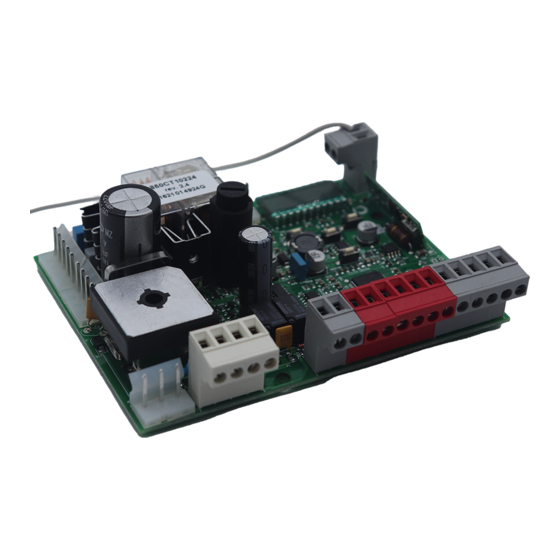
Control unit for a 24 vdc motor for sliding gate, roller door or boom barrier
Hide thumbs
Also See for CT102 24:

Subscribe to Our Youtube Channel
Related Manuals for Key Automation CT102 24


Summary of Contents for Key Automation CT102 24
- Page 1 CT102 24 Control unit for a 24 Vdc motor for sliding gate, roller door or boom barrier Management System ISO 9001:2008 www.tuv.com ID 9105043769...
-
Page 2: Table Of Contents
TABLE OF CONTENTS Safety warnings pag. 19 Introduzione al prodotto pag. 21 Descrizione della centrale pag. 21 Descrizione dei collegamenti pag. 21 Modelli e caratteristiche tecniche pag. 21 Elenco cavi necessari pag. 22 Preliminary Checks pag. 22 Installing the Product pag. - Page 3 During installation ensure that no liquids are able to enter the various devices; should this occur, disconnect the power supply immediately and contact a Key Automation Service Centre. Use of the automation...
- Page 4 The CT10224 control unit is the most modern, efficient system for has a display allowing easy programming and constant monitoring the control of Key Automation motors for the electric opening and of the input status; the menu structure also allows easy setting of closure of sliding gates, up-and-over doors and electromechanical working times and operating modes.
- Page 5 - Power supply with protection against short-circuits inside the con- - Safety device deactivation by means of dip switches: there is no trol unit, on motors and on the connected accessories. need to bridge the terminals of safety devices which are not instal- - Obstacle detection.
-
Page 6: Electric Connections
4 - PRODUCT INSTALLATION 4.1 - Electrical connections WARNING Before making the connections, ensure that the control unit is not powered up POWER SUPPLY CONNECTOR MOTOR CONNECTOR Power supply live 230 Vac (120 Vac) 50-60 Hz Power supply connection terminal board Power supply neutral 230 Vac (120 Vac) 50-60 Hz Power supply motor Earth... -
Page 7: Display During Normal Operation
SAFETY AND CONTROL DEVICE CONNECTOR Common for the FLASH-IND-LED inputs FLASH Flashing light output 24Vdc (without regulation), maximum 25W IND output for gate open indicator light 24 Vdc not regulated 4W MAX / Electric lock output 12Vac, 15VA maximum selectable with parameter IN.D. - Page 8 KEY TO MAIN CONTROL EVENT DESCRIPTION FLASHING LIGHT AND KEY LEDS CONTROL UNIT opening Gate opening closure Gate closing automatic closure Gate open with timed reclosure active stop during closure Gate stopped during closure stop during opening Gate stopped during opening open Gate completely open without automatic reclosure closed...
-
Page 9: Autolearning Of The Travel Stroke
4.3 - Autolearning of the travel stroke as the travel stroke length and deceleration points. The first time the control unit is powered up, an autolearning proce- dure must be carried out to acquire fundamental parameters such AUTOLEARNING OF THE TRAVEL STROKE AND MAIN PARAMETERS The decelerations will be those set in the menu, with the same percentage during both opening and closing. -
Page 10: Customising The System - Basic Menu
CLEARING THE ENTIRE RECEIVER MEMORY If you are in programming mode exit pressing the MENU button until -- appears. Press the DOWN (RADIO) button for more than 2 seconds. Until the display shows the word “rad” (radio), then release the button 1. - Page 11 PARAMETERS DESCRIPTION DEFAULT UNIT Automatic reclosure time (0 = off) Reclosing time after transit on PH1 (0 = off) Sensitivity on obstacles 0 = Maximum impact force 10 = Minimum impact force Motor speed during opening 1 = minimum 2 = low 3 = medium 4 = high 5 = maximum...
-
Page 12: Testing And Commissioning
5 - TESTING AND COMMISSIONING THE AUTOMATION SYSTEM The system must be tested by a qualified technician, who must per- regulatory requirements, especially the EN12445 standard which form the tests required by the relevant standards in relation to the specifies the test methods for gate and door automation systems. risks present, to check that the installation complies with the relevant 5.1 Testing All system components must be tested following the procedures de-... - Page 13 6 - FURTHER DETAILS - ADVANCED MENU The ADVANCED MENU allows the system to be further customised LEGENDA: by modifying parameters not accessible from the basic menu. SL= sliding gate To access the ADVANCED menu, press the MENU key and hold it BA= barrier down for 5 seconds.
- Page 14 PARAMETS DESCRIPTION DEFAULT UNIT TYPE Clearance. Allows to stop before the fully open position: it CL.E. BA/OH is useful to avoid mechanical stress during opening. Hold-to-run SL/BA/ de.a. 0 = off 1 = on 0 = deactivated 1 = gate open light ON/OFF 2 = gate open light proportional - Slow flashing with gate opening - Quick flashing with gate closing...
- Page 15 In the event of safety devices out of service arran- Thank you for choosing Key Automation S.r.l.; please visit our Inter- ge for repairs to the automation immediately;...
- Page 16 Key Automation S.r.l. Via A. Volta 30 - 30020 Noventa di Piave (VE) T. +39 0421.307.456 - F. +39 0421.656.98 Instruction version info@keyautomation.it - www.keyautomation.it 580ISCT10224 REV.07...
Need help?
Do you have a question about the CT102 24 and is the answer not in the manual?
Questions and answers