Key Automation CT102 Instructions And Warnings For Installation And Use
Control unit for a 230 vac (120 vac) motor, for a sliding gate or up-and-over door
Hide thumbs
Also See for CT102:
Table of Contents
Advertisement
Centrale per un motore 230 Vac (120 Vac), per cancello scorrevole o portone basculante
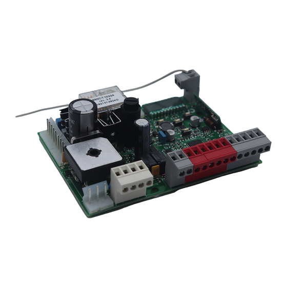
Control unit for a 230 Vac (120 Vac) motor, for a sliding gate or up-and-over door
Logique de commande pour un moteur 230 Vca (120 Vca), pour portail coulissant ou porte basculante
Central para un motor 230 Vca (120 Vca), para puerta de corredera o portón basculante
Steuergerät für einen Motor 230 Vac (120 Vac), für Schiebetor oder Schwingtor
Unidade para um motor 230 Vac (120 Vac), para portão de correr ou portão basculante
Centrala do silnika 230 Vac (120 Vac), napędzającego przesuwną bramę ogrodzeniową
Istruzioni ed avvertenze per l'installazione e l'uso
Instructions and warnings for installation and use
Instructions et avertissements pour l'installation et l'usage
Instrucciones y advertencias para su instalación y uso
Anleitungen und Hinweise zu Installation und Einsatz
Instruções e advertências para a instalação e utilização
Management
System
ISO 9001:2008
www.tuv.com
ID 9105043769
CT102
lub uchylną bramę garażową
Advertisement
Table of Contents

Related Manuals for Key Automation CT102


Summary of Contents for Key Automation CT102
- Page 1 Anleitungen und Hinweise zu Installation und Einsatz Instruções e advertências para a instalação e utilização CT102 Centrale per un motore 230 Vac (120 Vac), per cancello scorrevole o portone basculante Control unit for a 230 Vac (120 Vac) motor, for a sliding gate or up-and-over door Logique de commande pour un moteur 230 Vca (120 Vca), pour portail coulissant ou porte basculante Central para un motor 230 Vca (120 Vca), para puerta de corredera o portón basculante...
-
Page 2: Table Of Contents
TABLE OF CONTENTS Safety warnings pag. 15 Product Introduction pag. 16 Description of the control unit pag. 16 Description of the connections pag. 16 Models and technical characteristics pag. 16 List of cables required pag. 17 Preliminary Checks pag. 17 Installing the Product pag. -
Page 3: Safety Warnings
Read the instructions carefully before proceeding with installation. should this occur, disconnect the power supply immediately and contact a Key Automation Service Centre. Use of the automation The design and manufacture of the devices making up the system in these conditions may cause hazards;... -
Page 4: Description Of The Control Unit
Key Automation motors for the electric opening and closure times and operating modes. of sliding gates and up-and-over doors. All other, improper, use of the control unit is forbidden. The CT102 has 18 3 RECEIVER RX4X OUTPUT 1 = STEP BY STEP... -
Page 5: List Of Cables Required
- Power supply with protection against short-circuits inside the con- - Automatic learning of working times. trol unit, on motors and on the connected accessories. - Safety device deactivation by means of dip switches: there is no - Obstacle detection during travel at normal speed by means of cur- need to bridge the terminals of safety devices which are not instal- rent sensor. -
Page 6: Electric Connections
4 - PRODUCT INSTALLATION 4.1 - Electrical connections WARNING - Before making the connections, ensure that the control unit is not powered up. POWER SUPPLY CONNECTOR MOTOR CONNECTOR Power supply live 230 Vac (120 Vac) 50-60 Hz Power supply connection terminal board Power supply neutral 230 Vac (120 Vac) 50-60 Hz Motor live COM Vac Common of the “CR”... -
Page 7: Display During Normal Operation
SAFETY AND CONTROL DEVICE CONNECTOR +24 Vdc Accessories power supply positive 24 Vdc, 250 mA Accessories power supply negative + 24 Vdc Photocells PH1 and PH2 power supply positive; phototest can be selected with parameter tph 24 Vdc, 250 mA TX PHOTO EDGE Safety sensor edge, ON/OFF NC contact or resistive 8K2 between EDGE and EDGE (warning, with dip switch 1 ON the... -
Page 8: Autolearning Of The Travel Stroke
Malfunctions This section lists a number of malfunctions which may occur. SURGE OVERLOAD ALARM The motor’s current drawdown has increased very quickly 1. The gate has struck an obstacle. 2. Friction on runners or rack. SAFETY EDGE ALARM The control unit has received a signal from the safety edge 1. -
Page 9: Customising The System - Basic Menu
AUTOLEARNING OF THE TRAVEL STROKE AND MAIN PARAMETERS, WITH CUSTOMISED DECELERATIONS 1. Release the gate or door, move it onto the central position and lock it in place again. 2. Access the basic menu to set parameter LSI=P as shown in the table in point 4.4. 3. -
Page 10: Connecting The Radio Receiver
DEFAULT PARAMETERS DESCRIPTION UNIT CONFIGURATION Automatic reclosure time (0 = off) Reclosing time after transit (0 = off) Sensitivity on obstacles % (step (0 = off) of 1) % (step Motor force (peak torque) of 1) Deceleration mode 0 = 1/3 deceleration 1 = 2/3 deceleration SS configuration: 0 = Normal (AP-ST-CH-ST-AP-ST…) -
Page 11: Further Details - Advanced Menu
6 - FURTHER DETAILS - ADVANCED MENU The ADVANCED MENU allows the system to be further customised down for 5 seconds by modifying parameters not accessible from the basic menu To modify ADVANCED MENU parameters, proceed as described To access the ADVANCED menu, press the MENU key and hold it for the BASIC MENU DEFAULT PARAMETERS... -
Page 12: Instructions And Warnings For The
In the event of safety devices out of ser- Thank you for choosing Key Automation S.r.l.; please visit our Inter- vice arrange for repairs to the automation immediately;... - Page 13 NOTES...
Need help?
Do you have a question about the CT102 and is the answer not in the manual?
Questions and answers