Table of Contents
Advertisement
Quick Links
Instructions and warnings for installation and use
Istruzioni ed avvertenze per l'installazione e l'uso
Instructions et avertissements pour l'installation et l'usage
Instrucciones y advertencias para su instalación y uso
Instruções e advertências para a instalação e utilização
Instrukcje i zalecenia dotyczące instalacji i użytkowania
Anleitungen und Hinweise zu Installation und Einsatz
ON
STOP
PH2
PH1
OPEN CLOSE PAR
SBS
CT10324
Control unit for a 24 Vdc motor, for a sliding gate or up-and-over door
Centrale per un motore 24 Vdc, per cancello scorrevole o portone basculante
Logique de commande pour un moteur 24 Vdc, pour portail coulissant ou porte basculante
Central para un motor 24 Vdc, para puerta de corredera o portón basculante
Steuergerät für einen Motor 24 Vdc, für Schiebetor oder Schwingtor
Unidade para um motor 24 Vdc, para portão de correr ou portão basculante
Jednostka sterująca do silnika 24 Vdc obsługującego bramę przesuwną lub wahadłowe drzwi
Advertisement
Table of Contents

Subscribe to Our Youtube Channel
Related Manuals for Key Automation CT10324


Summary of Contents for Key Automation CT10324
- Page 1 Anleitungen und Hinweise zu Installation und Einsatz STOP OPEN CLOSE PAR CT10324 Control unit for a 24 Vdc motor, for a sliding gate or up-and-over door Centrale per un motore 24 Vdc, per cancello scorrevole o portone basculante Logique de commande pour un moteur 24 Vdc, pour portail coulissant ou porte basculante Central para un motor 24 Vdc, para puerta de corredera o portón basculante...
-
Page 3: Table Of Contents
INDEX 1 - Safety warnings 2 - Introducing the product 2.1 - Description of the control unit 2.2 - Description of the connections 2.3 - Models and technical characteristics 2.4 - List of cables required 3 - Preliminary checks 4 - Product installation 4.1 - Electrical connections 4.2 - Disabling the safety devices 4.3 - Display during normal operation... -
Page 4: Safety Warnings
Operations of this type KEY AUTOMATION S.r.l. reserves the right to amend these in- can only lead to malfunctions. The manufacturer declines all liability structions if necessary;... -
Page 5: Introducing The Product
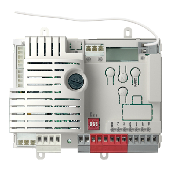
2 - INTRODUCING THE PRODUCT 2.1 - Description of the control unit The CT10324 control unit is the most modern and efficient control it easier to read the acronyms, facilitating programming and device for 24VDC Key Automation gear motors for sliding gates; any monitoring of the automation;... -
Page 6: List Of Cables Required
TECHNICAL SPECIFICATIONS CT10324 Power Supply 24 VAC (+10% -15%) 50/60 Hz Maximum motor power 200 W Maximum output current 24VAC 200 mA (24 VAC) PH-POW maximum output current 200 mA (24 VDC non-regulated) Maximum FLASH output power 15 W (24 VDC) -
Page 7: Product Installation
4 - PRODUCT INSTALLATION 4.1 - Electrical connections Before making the connections, ensure that the control unit is not powered up. WARNING ! MOTOR CONNECTION DIP SWITCH Power supply connection terminal board Set on “ON” to disable inputs EDGE, PH1, PH2 This procedure avoids to bridge the terminal board inputs. - Page 8 ELECTRICAL CONNECTIONS ELECTRICAL CONNECTIONS FOR PHOTO1 AND PHOTO2 FOR ENERGY SAVING POWER SUPPLY POWER SUPPLY 12/24 COM OUT 12/24 AC/DC AC/DC 12/24 12/24 COM OUT AC/DC AC/DC WARNING ! To enable paragraph 5.1, point 12. Only during this function PHOTOTEST is not possible SAFETY AND CONTROL DEVICE CONNECTORS 24 VAC Accessory power supply 24VAC non-regulated 200mA MAX;...
-
Page 9: Disabling The Safety Devices
4.2 - Disabling the safety devices EDGE The control unit provides (default setting) for the installation of a safety edge connected to the EDGE inputs; in the event of a missing or incorrect connection, the operation of the automation is inhibited. In a system where a safety edge is not to be installed, its use can be disabled by setting the EDGE dip-switch to ON. -
Page 10: Error Messages On The Display
4.3.1 - Error messages on the display To cancel the error message on the display, after having eliminated the cause of the anomaly, perform a complete opening or closing manoeuvre, i.e. until the relevant limit switch is reached. Alternatively, briefly press the MENU button (the automation does not perform any movement). -
Page 11: Autolearning Of The Travel Stroke And Main Parameters
4.4.1 - Autolearning of the travel stroke and main parameters 1. Unlock the gear motor, bring the gate to approximately half its travel and lock the gear motor again. 2. To start the auto-learning procedure, simultaneously press and hold the (UP) and ((MENU) buttons;... -
Page 12: Radio Remote Control Management
4.5 - Radio remote control management NOTE: to facilitate saving operations, thereby minimising To save the buttons of a radio remote control, delete them or delete all the saved radio remote controls, use the menu. To any interference, it is advisable to disconnect the receiver’s access the menu, press the (DOWN-RADIO) button for... -
Page 13: Deletion Of The Entire Receiver Memory
4.5.3 - Deletion of the entire receiver memory Exit any menu, press and hold the (DOWN-RADIO) button until the display alternately shows ► 1. Press and hold down the (DOWN-RADIO) button until the KEY LED lights up (approximately three ► seconds);... -
Page 14: System Customisation
5 - PERSONALIZZAZIONE DELL’IMPIANTO 5 - SYSTEM CUSTOMISATION The configuration menus of the equipment operating functions are divided into BASE and ADV (basic/advanced). The following tables show the description of each basic parameter with the respective minimum, maximum and default values. 1. -
Page 15: Advanced Parameters
Additional insertion/additional edge: 0 = disabled 1 = the PAR input becomes STOP NO 2 = the PAR input becomes STOP NC 3 = the PAR input becomes EDGE NC on opening 4 = the PAR input becomes EDGE 8K2 on opening 5 = the PAR input becomes EDGE 4K1 on opening WARNING to activate EDGE2, the TYPE EDGE... - Page 16 0 = EDGE1 intervenes only during closing with a short reversal 1 = EDGE1 intervenes during both closing and opening with a short reversal Attention: if the PAR input is used as EDGE2 then must be 0 Edge test 0 = disabled 1 = enabled Partial opening Partial automation re-closing time...
-
Page 17: Testing And Commissioning The Automation System
Enabling of continuous flashing for assistance request with ≠ 0 (function only performed when the gate is closed). 0 = disabled 1 = enabled Electric lock activation time if the electric lock is activated. Deactivation time of the magnetic electric lock if the magnetic lock is selected. -
Page 18: Instructions And Warnings For The End User
• before using the automation system for the first time, have the installer explain the potential causes of residual risks to you; Thank you for choosing Key Automation S.r.l.; please visit our Inter- net site www.keyautomation.com for further information. • keep the manual for future reference, and pass it on to any new owner of the automation system;... - Page 19 Il sottoscritto Nicola Michelin, Amministratore Delegato dell’azienda The undersigned Nicola Michelin, General Manager of the company Key Automation s.r.l., via Meucci 23, 30027 San Donà di Piave (VE) – ITALIA dichiara che il prodotto tipo: declares that the product type:...
- Page 20 Key Automation S.r.l. Via Meucci 23 - 30027 San Donà di Piave (VE) T. +39 0421 307456 - info@keyautomation.it Instruction version www.keyautomation.com 580CT10324 REV03...
Need help?
Do you have a question about the CT10324 and is the answer not in the manual?
Questions and answers