Table of Contents
Advertisement
Istruzioni ed avvertenze per l'installazione e l'uso
Instructions and warnings for installation and use
Anleitungen und Hinweise zu Installation und Einsatz
Instrucciones y advertencias para su instalación y uso
Instructions et avertissements pour l'installation et l'usage
Instruções e advertências para a instalação e utilização
Centrale per due motori 230 Vac (120 Vac), per cancelli a battente
Logique de commande pour deux moteurs 230 Vca (120 Vca), pour portails battants
Central para dos motores de 230 Vca (120 Vca) para puertas de batiente
Unidade para dois motores 230 Vac (120 Vac), para portões de batente
Centrala dla dwóch silników 230 Vac (120 Vac), do bram skrzydłowych
Control unit for two 230 Vac (120 Vac) motors, for swing gates
Steuergerät für zwei Drehtor-Motoren 230 Vac (120 Vac)
Management
System
ISO 9001:2008
www.tuv.com
ID 9105043769
UP
CT202
DOWN
MENU
SS
Advertisement
Table of Contents

Related Manuals for Key Automation CT202


Summary of Contents for Key Automation CT202
- Page 1 Instruções e advertências para a instalação e utilização DOWN MENU CT202 Centrale per due motori 230 Vac (120 Vac), per cancelli a battente Control unit for two 230 Vac (120 Vac) motors, for swing gates Logique de commande pour deux moteurs 230 Vca (120 Vca), pour portails battants Central para dos motores de 230 Vca (120 Vca) para puertas de batiente Steuergerät für zwei Drehtor-Motoren 230 Vac (120 Vac)
-
Page 2: Table Of Contents
TABLE OF CONTENTS Safety warnings pag. 15 Product Introduction pag. 16 Description of the control unit pag. 16 Description of the connections pag. 16 Models and technical characteristics pag. 16 List of cables required pag. 17 Preliminary Checks pag. 17 Installing the Product pag. -
Page 3: Safety Warnings
CAUTION – to ensure personal safety it is important should this occur, disconnect the power supply immediately and to follow these instructions and keep them for future contact a Key Automation Service Centre. Use of the automation reference. system in these conditions may cause hazards;... -
Page 4: Description Of The Control Unit
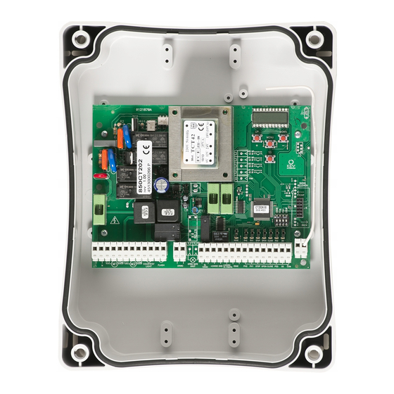
2.1 - Description of the control unit The CT202 control unit is a state-of-the-art efficient control system for CT202 control unit is equipped with a display to enable simple pro- Key Automation motors, for electrical opening and closing of swing gramming and constant monitoring of input status;... -
Page 5: List Of Cables Required
TECHNICAL SPECIFICATIONS: Power supply (L-N) 230 Vac (+10% - 15%) 50-60 Hz 120 Vac (+10% - 15%) 50-60 Hz Max motor load 700 W + 700 W 700 W + 700 W Output for Vdc accessories power and device test power 24 Vdc 500 mA 24 Vdc 500 mA Output for Vac accessories power... -
Page 6: Electric Connections
4 - PRODUCT INSTALLATION 4.1 - Electrical connections WARNING - Before making the connections, ensure that the control unit is not powered up. POWER SUPPLY CONNECTOR AND MOTOR POWER SUPPLY CONNECTOR 230 Vac (120 Vac) 50-60 Hz power supply phase Set on “ON”... -
Page 7: Display During Normal Operation
SAFETY AND CONTROL DEVICE CONNECTOR 24 Vac Accessories power 24 Vac, 1 A EL 12 Vac Electric lock output 12 Vac / 15 VA +24 Vdc Accessories power positive 24 Vdc, 500 mA Accessories power negative 24 Vdc, 500 mA + 24 Vdc Power positive for photocells PH1, PH2;... -
Page 8: Autolearning Of The Travel Stroke
Malfunctions This section lists a number of malfunctions which may occur. SURGE OVERLOAD ALARM The motor’s current drawdown has increased very quickly 1. Leaf impact with obstacle. 2. Gate rubs during opening/closing SAFETY EDGE ALARM The control unit has received a signal from the safety edge 1. - Page 9 10. Motors M1 and M2 resume closing according to the leaf offset values set in the menu, i.e. the gate closes automatically according to the set travel. 11. Run a number of opening, closing and stop manoeuvres, to check that the system is stable and there are no assembly defects.
-
Page 10: Customising The System - Basic Menu
4.4 - Customising the system - BASIC MENU If necessary, users may select a BASIC MENU which allows modi- WARNING: to be certain of accessing the NORMAL OPERATION fication of the control unit’s basic parameters. To select the BASIC display state, the starting point for accessing the BASIC MENU, MENU proceed as described below. -
Page 11: Testing And Commissioning
5 - TESTING AND COMMISSIONING THE AUTOMATION SYSTEM The system must be tested by a qualified technician, who must relevant regulatory requirements, especially the EN12445 standard perform the tests required by the relevant standards in relation to which specifies the test methods for gate and door automation sy- the risks present, to check that the installation complies with the stems. -
Page 12: Further Details - Advanced Menu
6 - FURTHER DETAILS - ADVANCED MENU The ADVANCED MENU allows the system to be further customised down for 5 seconds by modifying parameters not accessible from the basic menu To modify ADVANCED MENU parameters, proceed as described To access the ADVANCED menu, press the MENU key and hold it for the BASIC MENU DEFAULT PARAMETERS... -
Page 13: Instructions And Warnings For The
In the event of safety devices out of ser- Thank you for choosing Key Automation S.r.l.; please visit our Inter- vice arrange for repairs to the automation immediately;...
Need help?
Do you have a question about the CT202 and is the answer not in the manual?
Questions and answers