Advertisement
Quick Links
Istruzioni ed avvertenze per l'installazione e l'uso
Instructions and warnings for installation and use
Instructions et avertissements pour l'installation et l'usage
Anleitungen und Hinweise zu Installation und Einsatz
Instrucciones y advertencias para su instalación y uso
Instruções e advertências para a instalação e utilização
Instrukcje i zalecenia dotyczące instalacji i użytkowania
CT20224
CT20224E
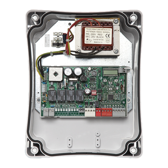
Centrale per due motori 24 Vdc, per cancelli a battente
Control unit for two 24 Vdc motors, for swing gates
Logique de commande pour deux moteurs 24 Vdc, pour portails battants
Central para dos motores de 24 Vdc para puertas de batiente
Steuergerät für zwei Drehtor-Motoren 24 Vdc
Unidade para dois motores 24 Vdc, para portões de batente
Centrala dla dwóch silników 24 Vdc, do bram skrzydłowych
Advertisement

Subscribe to Our Youtube Channel
Related Manuals for Key Automation CT20224


Summary of Contents for Key Automation CT20224
- Page 1 Instrucciones y advertencias para su instalación y uso Instruções e advertências para a instalação e utilização Instrukcje i zalecenia dotyczące instalacji i użytkowania CT20224 CT20224E Centrale per due motori 24 Vdc, per cancelli a battente Control unit for two 24 Vdc motors, for swing gates...
- Page 2 INDEX Safety warnings p. 19 Introducing the product p. 21 Description of the control unit p. 21 Description of the connections p. 21 Models and technical characteristics p. 21 List of cables required p. 22 Preliminary checks p. 22 Product installation p.
- Page 3 If in any doubt regarding installation, do not proceed and con- tact the Key Automation Technical Service for clarifications. do not allow parts of the automation system to be im- mersed in water or other liquids. During installation...
- Page 4 Key Automation reserves the right to amend electrical mains; these instructions if necessary; they and/ special care must be taken to avoid crushing between...
- Page 5 2 - INTRODUCING THE PRODUCT 2.1 - Description of the control unit The CT20224 control unit is the most modern, efficient system for CT20224 has a display allowing easy programming and constant the control of Key Automation motors for the electric opening and monitoring of the input status;...
- Page 6 TECHNICAL SPECIFICATIONS CT202 24 CT202 24E CT202 24L Power supply (L-N) 230Vac (+10% - 15%) 50/60 Hz 115Vac (+10%-15%) 50/60 Hz Rated power maximum 210W maximum 280W maximum 210W Photocell power supply output 24Vdc (without regulation) maximum 250mA Output for Vac accessories power 24 Vac without regulation 200 mA / 24 Vdc without regulation 250 mA Flashing light output 24Vdc (without regulation) 15W...
- Page 7 4 - PRODUCT INSTALLATION 4.1 - Electrical connections WARNING - Before making the connections, ensure that the control unit is not powered up. MOTOR CONNECTION POWER SUPPLY CONNECTOR Power supply connection terminal board Power supply live 230 Vac (120 Vac) 50-60 Hz M1 + Power supply of motor M1 + Power supply neutral 230 Vac (120 Vac) 50-60 Hz...
- Page 8 ELECTRICAL CONNECTIONS FOR ENERGY SAVING SAFETY AND CONTROL DEVICE CONNECTORS 24 VAC Accessories power supply 24 Vac without regulation, 200 mA (with battery operation output not active) 24 VAC Accessories power supply 24 Vac without regulation, 200 mA (with battery operation output not active) Common for the FLASH-IND-LED outputs FLASH Flashing light output 24Vdc (without regulation), maximum 15W...
- Page 9 MESSAGES MEANING Re-alignment procedure Gate stopped without automatic reclosure Gate in partial opening mode Gate in partial opening position without automatic reclosure Gate open with timed reclosure - Flashing dash counting in progress Dash replaced by figures 0..9 countdown (last 10s) Gate in partial opening position with timed reclosure - Flashing dash counting in progress Dash replaced by figures 0..9 countdown (last 10s) Learning stopped due to activation of safety device or motor inversion...
- Page 10 4.3 - Autolearning of the travel stroke The first time the control unit is powered up, an autolearning such as the travel stroke length and deceleration points. procedure must be carried out to acquire fundamental parameters AUTOLEARNING OF THE TRAVEL STROKE AND MAIN PARAMETERS The decelerations will be those set in the menu, with the same percentage during both opening and closing.
- Page 11 7. On reaching the point where motor M2 closing deceleration is required, press SBS. M2 motor movement continues at low speed (the display shows SC.L.) 8. On reaching the mechanical end stop of motor M2, motor M1 starts closing 9. On reaching the point where motor M1 closing deceleration is required, press SBS. M1 motor movement continues at low speed (the display shows SCL) 10.
- Page 12 DELETING A REMOTE CONTROL If you are in programming mode exit pressing the MENU button until -- appears. Press the DOWN (RADIO) button for more than 2 seconds. Until the display shows the word “rad” (radio), then release the button 1.
- Page 13 DOWN DOWN DOWN MENU MENU MENU Press the MENU button Press the + and – buttons to Press the MENU button quickly for 1 second to display the scroll through the functions to to quit the menu. parameter in order to save modify other parameters.
- Page 14 5 - TESTING AND COMMISSIONING THE AUTOMATION SYSTEM The system must be tested by a qualified technician, who must the relevant regulatory requirements, especially the EN12445 perform the tests required by the relevant standards in relation standard which specifies the test methods for gate and door to the risks present, to check that the installation complies with automation systems.
- Page 15 PARAMETERS DESCRIPTION DEFAULT UNIT Edge test tE.D. 0 = off 1 = on LP.o. Partial opening Time for automatic closure from partial opening TP.C. (0=off) Flashing light output setup FP.r. 0 = Steady 1 = Flashing tP.r. Pre-flashing time (0 = off) Courtesy light setup 0 = On at end of operation for time TCY FC.Y.
- Page 16 7 - INSTRUCTIONS AND WARNINGS FOR THE END USER Key Automation S.r.l. produces systems for the automation of gates, • manual release and operation: first bear in mind that the release garage doors, automatic doors, roller blinds and car-park and road procedure can only be carried out with the door or gate stationery.
- Page 17 NOTE...
- Page 18 8 - DECLARATION OF CONFORMITY...
- Page 20 Key Automation S.r.l. Via Meucci 23 - 30027 San Donà di Piave (VE) T. +39 0421 307456 - F. +39 0421 65698 Instruction version info@keyautomation.it - www.keyautomation.it 580CT20224E REV.04...
Need help?
Do you have a question about the CT20224 and is the answer not in the manual?
Questions and answers