Table of Contents
Advertisement
Quick Links
Istruzioni ed avvertenze per l'installazione e l'uso
Instructions and warnings for installation and use
Instructions et avertissements pour l'installation et l'usage
Anleitungen und Hinweise zu Installation und Einsatz
Instrucciones y advertencias para su instalación y uso
Instruções e advertências para a instalação e utilização
Instrukcje i zalecenia dotyczące instalacji i użytkowania
CT102 24
Centrale per un motore 24 Vdc, per cancello scorrevole, portone basculante o barriera
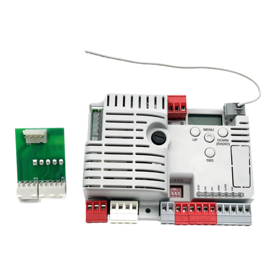
Control unit for a 24 Vdc motor, for a sliding gate, up-and-over door or barrier
Logique de commande pour un moteur 24 Vdc, pour portail coulissant, porte basculante ou barrieres
Central para un motor 24 Vdc, para puerta de corredera, portón basculante o barreras
Steuergerät für einen Motor 24 Vdc, für Schiebetor, Schwingtor oder Schrankenöffnung
Unidade para um motor 24 Vdc, para portão de correr, portão basculante ou barreira
Centrala do silnika 24 Vdc, napędzającego przesuwną bramę ogrodzeniową,
uchylną bramę garażową lub szlaban
Advertisement
Table of Contents

Related Manuals for Key Automation 850CT10224


Summary of Contents for Key Automation 850CT10224
- Page 1 Istruzioni ed avvertenze per l’installazione e l’uso Instructions and warnings for installation and use Instructions et avertissements pour l’installation et l’usage Anleitungen und Hinweise zu Installation und Einsatz Instrucciones y advertencias para su instalación y uso Instruções e advertências para a instalação e utilização Instrukcje i zalecenia dotyczące instalacji i użytkowania CT102 24 Centrale per un motore 24 Vdc, per cancello scorrevole, portone basculante o barriera...
- Page 2 INDEX Safety warnings pag. 18 Introducing the product pag. 20 Description of the control unit pag. 20 Description of the connections pag. 20 Models and technical characteristics pag. 20 List of cables required pag. 21 Preliminary checks pag. 21 Product installation pag.
-
Page 3: Safety Warnings
If in any doubt regarding installation, do not proceed if the power cable is damaged, it must be replaced by and contact the Key Automation Technical Service for the manufacturer or its after-sales service, or in all ca- clarifications. - Page 4 Key Automation reserves the right to amend fixed parts around it; these instructions if necessary; they and/...
-
Page 5: Introducing The Product
The CT10224 control unit is the most modern, efficient system for All other, improper, use of the control unit is forbidden. The CT10224 the control of Key Automation motors for the electric opening and has a display allowing easy programming and constant monitoring closure of sliding gates, up-and-over doors and electromechanical of the input status;... -
Page 6: Technical Specifications
TECHNICAL SPECIFICATIONS Power supply (L-N) 230 Vac (+10% - 15%) 50-60 Hz Max motor load 150 W Output for Vac accessories power 24 Vac without regulation 200 mA Device test power Vdc 24 Vdc without regulation 250 mA Courtesy light output 24 Vdc 25 W Flashing light output 24 Vdc 25 W... -
Page 7: Product Installation
4 - PRODUCT INSTALLATION 4.1 - Electrical connections ATTENTION - Before making the connections, ensure that the control unit is not powered up. MOTOR CONNECTOR DIP SWITCH Set on “ON” to disable inputs STOP, PH1, PH2 Power supply connection terminal board Eliminates the need to bridge the terminal board inputs. - Page 8 ELECTRICAL CONNECTIONS FOR ENERGY SAVING POWER SUPPLY POWER SUPPLY 230Vac 50/60Hz 12/24 12/24 COM OUT AC/DC AC/DC FLASH 12/24 12/24 COM OUT AC/DC AC/DC CONNECTOR SAFETY AND CONTROL DEVICE Common for the FLASH-IND-LED inputs FLASH Flashing light output 24Vdc (without regulation), maximum 25W IND output for gate open indicator light 24 Vdc not regulated 4W MAX / Electric lock output 12Vac, 15VA maximum selectable with parameter IN.D.
- Page 9 MESSAGES MEANING Photocell 1 tripped Photocell 2 tripped Gate stopped by external event Re-alignment procedure Gate stopped without automatic reclosure Gate in parcial opening mode Gate in parcial opening position without automatic reclosure Gate open with timed reclosure Flashing dash counting in progress Dash replaced by figures 0..9 countdown (last 10s) Gate in parcial opening position with timed reclosure Flashing dash counting in progress...
-
Page 10: Memorising A Remote Control
PHOTOCELL ALARM/SAFETY EDGE Phototest fail outcome. 1. Check the photocell and the safety edge connections. 2. Check that the photocells and the safety edg are operating correctly. ENCODER ALARM Encoder encoder (only if encoder is present) 1. Check the encoder connections. 2. -
Page 11: Deleting A Remote Control
DELETING A REMOTE CONTROL If you are in programming mode exit pressing the MENU button until -- appears. Press the DOWN (RADIO) button for more than 2 seconds. Until the display shows the word “rad” (radio), then release the button 1. - Page 12 DOWN DOWN DOWN MENU MENU MENU Press the MENU button Press the + and – buttons to Press the MENU button quickly for 1 second to display the scroll through the functions to to quit the menu. parameter in order to save modify other parameters.
-
Page 13: Further Details - Advanced Menu
5 - TESTING AND COMMISSIONING THE AUTOMATION SYSTEM The system must be tested by a qualified technician, who must the relevant regulatory requirements, especially the EN12445 perform the tests required by the relevant standards in relation standard which specifies the test methods for gate and door to the risks present, to check that the installation complies with automation systems. - Page 14 PARAMETERS DESCRIPTION DEFAULT MIN MAX UNIT TYPE Sensitive edge tripping mode 0= only tripped during closure with direction reversal SL/BA/ iE.D. 1 = stops the automation (during both opening and closure) and retreats from the obstacle Edge test SL/BA/ tE.D. 0 = off 1 = on LP.o.
- Page 15 PARAMETRI DESCRIZIONE DEFAULT MIN MAX UNITÀ Enabling of continuous flashing indicating service required with se.r. ≠ 0 (only active with gate SL/BA/ se.f. closed). 0 = off 1 = on SL/BA/ EL.T. Electric lock activation time in seconds High-speed motor start-up. SL/BA/ ST.P.
- Page 16 7 - INSTRUCTIONS AND WARNINGS FOR THE END USER Key Automation S.r.l. produces systems for the automation of gates, Arrange a periodic maintenance schedule with your installation garage doors, automatic doors, roller blinds and car-park and road engineer. Key Automation recommends that maintenance checks barriers.
-
Page 17: Declaration Of Conformity
24Vdc control unit for 1 motor with 433,92MHz built-in radio receiver Modello: Model: 850CT10224, 900CT10224, 850CT10224F E’ conforme a quanto previsto dalle seguen� dire�ve comunitarie: Is in conformity with the following community (EC) regulations: Dire�va macchine / Machinery Directive 2006/42/EC Dire�va compa�bilità... - Page 18 Key Automation S.r.l. Via Meucci 23 - 30027 San Donà di Piave (VE) T. +39 0421 307456 - F. +39 0421 65698 Instruction version info@keyautomation.it - www.keyautomation.it 580ISCT10224 REV.12...
Need help?
Do you have a question about the 850CT10224 and is the answer not in the manual?
Questions and answers