Otto Bock C1000 DS Service Instructions Manual
Hide thumbs
Also See for C1000 DS:
- Instructions for use manual (240 pages) ,
- Instructions for use manual (80 pages)
Table of Contents
Advertisement
Quick Links
Advertisement
Table of Contents

Related Manuals for Otto Bock C1000 DS


Summary of Contents for Otto Bock C1000 DS
- Page 1 C1000 DS Service Instructions...
-
Page 3: Table Of Contents
C1000 DS Service Instructions Table of Contents Page 1 General Information ......................7 1.1 Foreword .........................7 1.2 Support ........................7 2 Safety..........................7 2.1 Explanation of symbols ..................7 2.2 General safety information ..................7 2.3 Safety instructions for the use of tools and accessories ........8 2.4 Safety instructions for service and maintenance tasks .........9 2.5 S afety standards for maintenance tasks on electrical components ....11 2.6 ... - Page 4 6.8 Wheels ........................34 6.8.1 Inspecting the general condition ................34 6.8.2 Removing the drive wheel ..................34 6.8.3 Removing the steering caster .................35 6.8.4 Changing tyres ......................36 6.8.5 Replacing the casing and / or tube .................36 6.8.6 Removing the splash guard for the drive wheel ............37 6.8.7 Removing the holder for the drive wheel splash guard ..........38 6.8.8 Removing the splash guard for the steering caster ..........39 6.8.9 Replacing the wheel flange ..................39 6.9 Removing the spring, adjusting the spring power ..........39 6.9.1 Removing the drive wheel spring ................40 6.9.2 Removing the steering rocker spring ..............41 6.9.3 Adjusting the spring power ..................41 6.10 ...
- Page 5 6.15.14 Lap belt .........................67 6.15.15 Retrofitting arm straps..................68 6.15.16 Installing the contour seat (option) ..............69 6.15.17 Installing the Recaro® seat (option)..............69 6.15.18 Adapting / replacing the footrests ............... 71 6.15.19 Replacing the footplate ..................74 6.16 Electric seat functions ..................75 6.16.1 Retrofitting the electric back angle adjustment (option) ........75 6.16.2 Retrofitting the electric seat tilt (option) ..............76 6.16.3 Retrofitting the seat height adjustment (option) ...........77 6.16.4 Retrofitting the combination seat height adjustment / seat tilt (option)....78 6.16.5 Retrofitting electric footrests (option) ..............78 6.16.6 Retrofitting a seat module ..................79 6.16.7 Removing the seat tilt actuator ................80 6.16.8 Removing the back angle adjustment actuator ............ 81 6.16.9 ...
- Page 6 8.3 Seat module .......................105 8.3.1 Wiring the seat module ..................106 8.3.2 Electrical specifications ..................107 8.4 Programming device ..................108 8.4.1 Handheld programming device ................108 8.4.2 PC Programming Station (PCPS) ................110 8.5 Programmable parameters ................110 8.5.1 Main parameters .....................111 8.5.2 “Driving” parameter settings ................. 115 8.5.3 “Joystick” parameter settings ................119 9 Maintenance and Service Plan C1000 DS ..............121...
-
Page 7: General Information
These service instructions describe all regular maintenance tasks as well as repair and replace- ment tasks for the C1000 DS power wheelchair from Otto Bock. They include all information required by authorised personnel in order to correct functional and mechanical defects on com- ponents of the power wheelchair. -
Page 8: Safety Instructions For The Use Of Tools And Accessories
Risk of damage due to overloading / excessive strain. The maximum load capacity for the standard version of the C1000 DS power wheelchair is 140 kg. It is possible to have the power wheelchair ret- rofitted for a maximum load capacity of 200 kg. If the power wheelchair is equipped with a seat height adjustment unit, the maximum load capacity is 130 kg, optional 200 kg. -
Page 9: Safety Instructions For Service And Maintenance Tasks
CAUTION Risk of health impairment due to the use of improper work clothing. Ensure legally prescribed pro- tective work clothing is worn. CAUTION Risk of injury during tasks that involve lifting. When repair and maintenance tasks must be completed under raised parts or equipment, ensure suitable precautions are taken to secure the applicable com- ponents against falling. - Page 10 • If creep speed is not automatically activated when the seat height adjustment function is operated, an error has occurred. Any such errors must be promptly corrected by personnel authorised and trained by Otto Bock. The power wheelchair may only be used with the seat in its lowest position until the problem is corrected.
-
Page 11: S Afety Standards For Maintenance Tasks On Electrical Components
Risk of injury while working on the battery. • Only use a battery charger supplied by Otto Bock which has been tested and approved for the re- spective batteries by Otto Bock (observe information on the charger). Failure to do so can result in a battery explosion and possible impairment of health due to contact with battery acid. - Page 12 CAUTION Risk of injury due to uncontrolled movements. The fuse must always be removed for any mainte- nance work where the battery cover is open. CAUTION Risk of injury during tasks that involve lifting. The weight of a battery is approximately 20 kg. Use hoisting devices of sufficient capacity to remove or install the batteries or carry out these tasks with the aid of an assistant.
-
Page 13: Safety Functions
/ programming is complete. Programming must only be completed by author- ised personnel. Neither Otto Bock nor the control unit manufacturer are liable for damages (especially in combination with special controls) caused by programming that was not properly / professionally adapted to the abilities of the wheelchair user. -
Page 14: Transportation And Storage
The eyebolts at the font and back of the power wheelchair serve as mounting points for ten- sioning straps. Before transporting the C1000 DS power wheelchair, switch off the control unit and engage the wheel lock. fig. 1 Eyebolts front, eyebolts rear... -
Page 15: Folding For Transportation
3.1.1 folding for transportation 1. Flip up and remove the footrests. 2. Remove the side panels (see Section 6.15.9). 3. Fold down the back rest / back rest with electrical back angle adjustment (see Section 3.1.2 / 3.1.3). fig. 2 folding the footrests up 3.1.2 folding the back rest 1. -
Page 16: Folding The Back Rest With Electric Back Angle Adjustment
3.1.3 folding the back rest with electric back angle adjustment 1. Remove the side panels (see Section 6.15.9). 2. Push the lever up and unlock the cross bolt at the lower end of the drive unit. 3. Remove the cross bolt from the holder. 4. -
Page 17: Storage
Remove the fuse for shipping or when the power wheelchair is not being used for an extended period of time. The C1000 DS power wheelchair must be stored in an enclosed room. Remove the main fuse; otherwise, there is a risk of deep discharge. -
Page 18: Required Tools And Accessories
4 Required Tools and Accessories Suitable tools and accessories for the completion of service tasks are listed below: ❒ Flat screwdrivers, blade widths: 2.5/3.5/5.5 mm ❒ Phillips screwdriver, size: 2 ❒ Reversible ratchet handle wrench and sockets, sizes: 8 – 20 ❒... -
Page 19: Information Display
fig. 7 Handheld programming device 5 Information Display INfORMATION Please see Section 7 and 8 for information on the display of error messages using the control panel display / LCD monitor or the handheld programming device / PC software. Messages are shown on the control panel display or LCD monitor: Display symbol(s) LCD monitor display function... - Page 20 Coupled electric seat adjustment (back rest and seat tilt) Special functions, e.g. coupled electric seat adjustment (back adjustment and seat tilt) Seat height adjustment Electric footrests, coupled Electric footrest, left Electric footrest, right Drive-away lock Creep speed Attendant control Table 1: Information display on the control panel...
-
Page 21: Service And Maintenance
6 Service and Maintenance 6.1 Inspecting the general condition ❒ Check all safety-related components for corrosion, repair if required and reapply corrosion protection. ❒ Check weld seams. ❒ Check tightness of screw connections; replace thread-locking compound if required; ob- serve defined torque specifications; replace defective screws (e.g. in case of corrosion). ❒... -
Page 22: Batteries
In its standard configuration, the C1000 DS power wheelchair is equipped with two mainte- nance-free 12 V gel batteries with a capacity of 63 Ah. The batteries are located under the seat of the power wheelchair. - Page 23 • Only use a battery charger supplied by Otto Bock which has been tested and approved for the re- spective batteries by Otto Bock (observe information on the charger). Failure to do so can result in a battery explosion and possible impairment of health due to contact with battery acid.
- Page 24 1 Charging receptacle 2 Battery charger plug fig. 10 Otto Bock charger The battery charger features a programmed recharging phase. Once a discharged battery is completely charged (after approximately 8 hours), the battery charger can remain connected with no risk of overcharging or damaging the battery.
-
Page 25: Removing The Battery Cover
The battery charger indicates the following states: Display function Green LED flashing Low-maintenance battery Maintenance-free battery Steady Battery is charged to 80 % Yellow LED is illuminated Battery is charging Green LED is illuminated Battery is fully charged Red LED is illuminated Battery is defective or missing, or charging time has been exceeded Table 2: Battery capacity indicator on the battery charger If none of the LEDs are lit, there is no power supply. -
Page 26: Replacing The Batteries
6.3.3 Replacing the batteries NOTICE Risk of battery damage. Ensure correct polarity is used when connecting the batteries. The black ca- ble must be connected to the negative pole and the red cable to the positive pole. Preparation: ❒ Turn the control unit off. ❒... -
Page 27: Changing The Battery Installation Position
Risk of tipping due to changes in the centre of gravity. Changing the battery position also changes the centre of gravity of the C1000 DS. There is a risk that the steering casters may loose ground con- tact and the front anti-tipper may engage. -
Page 28: Reinstalling The Battery Cable
Preparation: ❒ Turn the control unit off. ❒ Remove the fuse (see Section 6.2). ❒ Remove the battery cover (see Section 6.3.2). ❒ Remove the battery (see Section 6.3.3). Tools: ❒ Allen wrench, size 4 Steps: 1. Loosen and remove two Allen head screws. 2. -
Page 29: Replacing The Charging Receptacle
Steps: 1. Remove the cover from the controller (see Section 6.6). 2. Disconnect the battery cable from the controller. 3. Open the cable ties. 4. Remove the battery cable and replace if required. Properly reassemble all components upon completion of the work. fig. -
Page 30: Luggage Carrier
5. Pull out the charging receptacle including cable towards the front and replace if required. Properly reassemble all components upon completion of the work. fig. 17 Charging receptacle including cable 6.5 Luggage carrier 6.5.1 Replacing the luggage carrier Tools: ❒ Open-end or combination wrench, size 13 ❒... -
Page 31: Adjusting The Luggage Carrier
19 Adjusting the luggage carrier 6.6 Replacing the controller In the C1000 DS power wheelchair, the controller is located at the rear below the luggage carrier. INfORMATION When connecting the cables, ensure correct assignment. The longer cable must be connected on the right in the direction of travel. - Page 32 Properly reassemble all components upon completion of the work. fig. 20 Removing the controller cover, removing the controller 1 2 3 4 fig. 21 Connections on the controller 1 Connector for steering motor left, behind that connection for steering potentiometer left 2 Connector for steering motor right, behind that connection for steering potentiometer right 3 Lighting connector 4 Connector for battery capacity indicator cable...
-
Page 33: Replacing The Seat Module
6.7 Replacing the seat module In the C1000 DS power wheelchair, the seat module is located at the rear below the luggage carrier. INfORMATION When connecting the cables, ensure correct assignment. Preparation: ❒ Turn the control unit off. ❒ Remove the fuse (see Section 6.2). -
Page 34: Wheels
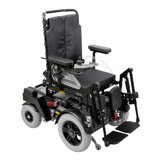
Replace the casing of pneumatic tyres if it is bald or shows signs of cracking or other damage. The C1000 DS power wheelchair is propelled by two 14” drive wheels and steered by means of two 10” steering casters. -
Page 35: Removing The Steering Caster
INfORMATION When reassembling the wheel, tighten the screws to a torque of 25 Nm. fig. 23 Removing the drive wheel 6.8.3 Removing the steering caster NOTICE Risk of damage due to uncontrolled movements. When raising the power wheelchair, e.g. with a jack, secure it against slipping and tipping sideways by using a suitable block under the drive unit sustainer. -
Page 36: Changing Tyres
INfORMATION When reassembling the steering caster, tighten the screw to a torque of 25 Nm. fig. 24 Removing the steering caster 6.8.4 Changing tyres Preparation: ❒ Remove the wheel (see Section 6.8.2 or 6.8.3). Tools: ❒ Tyre lever Steps: 1. Let all the air out of the tyre. 2. -
Page 37: Removing The Splash Guard For The Drive Wheel
Steps: 1. For pneumatic tyres: Let all air out of the tyre. 2. Loosen and remove five Allen head screws connecting the two sections of the wheel rim. 3. Pry back the casing from the edges of the rim. 4. For pneumatic tyres: Press the valve to the inside through the rim. 5. -
Page 38: Removing The Holder For The Drive Wheel Splash Guard
fig. 26 Removing the splash guard for the drive wheel 6.8.7 Removing the holder for the drive wheel splash guard Preparation: ❒ Remove the drive wheel (see Section 6.8.2). ❒ Remove the splash guard for the drive wheel (see Section 6.8.6). Tools: ❒... -
Page 39: Removing The Splash Guard For The Steering Caster
6.8.9 Replacing the wheel flange CAUTION Risk of accidents and injury due to improper completion of work on the wheel flange. The removal and installation of the wheel flange may only be completed in the plant of Otto Bock Manufacturing Königsee GmbH. 6.9 Removing the spring, adjusting the spring power NOTICE Risk of damage due to improper preparation of maintenance tasks. -
Page 40: Removing The Drive Wheel Spring
Standard / Seat Height Option Adjustment Chassis load capacity 140 kg /130kg 200 kg Spring stiffness, drive 170 lbs / in 250 lbs / in Spring stiffness, steering 650 lbs / in 750 lbs / in Table 3: Suspension 6.9.1 Removing the drive wheel spring The drive wheel spring is mounted at two points and connects the drive unit sustainer to the drive motor holder. -
Page 41: Removing The Steering Rocker Spring
6.9.2 Removing the steering rocker spring The spring on the steering rocker is attached to the drive unit sustainer at two points. Tools: ❒ Allen wrench, size 6 ❒ Open-end or combination wrench, size 13 Steps: 1. Loosen and remove the rear screw holding the spring to the steering rocker. 2. -
Page 42: Steering
fig. 31 Adjusting the spring power 1 Drive wheel spring plate 2 Steering rocker spring plate 6.10 Steering 6.10.1 Replacing the steering potentiometer Tools: ❒ Allen wrench, size 2.5 ❒ Side cutting pliers Steps: 1. Loosen and remove two Allen head screws on the cover. fig. -
Page 43: Replacing The Steering Motor
fig. 33 Removing the cover for the steering potentiometer 5. Move the steering potentiometer to the side and lay it down. fig. 34 Laying down the steering potentiometer 6. Open the cable ties. 7. Disconnect the cables to the steering motor and controller. 8. - Page 44 Steps: 1. Loosen and remove two Allen head screws on the small mounting plate. fig. 35 Removing the small mounting plate 2. Remove the small mounting plate. 3. Lift and remove the larger mounting plate below. fig. 36 Removing the larger mounting plate...
- Page 45 4. Remove the spacers. fig. 37 Removing the spacers 1 Spacers 5. Open and remove the retaining ring. fig. 38 Removing the retaining ring 6. With counter-support on the oscillating crank, remove the toothed wheel upwards. fig. 39 Removing the toothed wheel...
- Page 46 7. Remove the spring washers. fig. 40 Removing the spring washers 8. Secure the oscillating crank against falling with one hand and gently tap it out towards the floor. fig. 41 Tapping out the oscillating crank 9. Gently tap out the bearing towards the floor. fig.
- Page 47 10. Disconnect the cables to the controller. 11. Loosen and remove three Allen head screws on the steering motor. fig. 43 Loosening the Allen head screws on the steering motor 12. Remove the steering motor and replace if required. fig. 44 Removing the steering motor Properly reassemble all components upon completion of the work.
-
Page 48: Replacing The Steering Rocker
fig. 45 Spring on the steering motor 1 Groove 2 Toothed wheel 6.11 Replacing the steering rocker Preparation: ❒ Remove the steering caster (see Section 6.8.3). ❒ Remove the steering (see Section 6.10). ❒ Remove the steering rocker spring (see Section 6.9.2). ❒ Remove the rear lighting (see Section 6.14.2) Tools: ❒... -
Page 49: Wheel Lock And Wheel Lock Release
Both drive motors of the C1000 DS power wheelchair are simultaneously braked by the control unit via a motor brake. In case of defects in the brake system, the motor brake can only be re- placed as a unit with the drive motor. -
Page 50: Setting / Adjusting The Wheel Lock Release
Repairs and settings must only be made by authorised personnel. Re- place damaged Bowden cables with new ones immediately. Correct wheel lock settings are essential for safe driving. This is why Otto Bock recommends inspecting the wheel lock every three months. - Page 51 When making adjustments for the first time (e.g. cable replacement), the Bowden cable should have very little play before adjusting it. INfORMATION Lock the adjustment screw every time the setting is changed. Otto Bock recommends changing the setting in small increments (½ turn). Tools: ❒...
-
Page 52: Performing A Function Check Of The Wheel Lock Settings
fig. 50 Attachment of the Bowden cables on the drive motors 1 Threaded rod for readjustment 6.12.3 Performing a function check of the wheel lock settings During the functional test of the wheel lock settings, please observe the following points and complete the tasks described below: Steps: 1. -
Page 53: Anti-Tipper
6.13 Anti-tipper The C1000 DS power wheelchair is equipped with an anti-tipper as standard equipment. It is only installed in pairs (drive side, one on the left and right of the drive unit sustainer, respectively). 6.13.1 Removing the anti-tipper holder Tools: ❒... -
Page 54: Lighting
Removing the anti-tipper wheel 6.14 Lighting The C1000 DS power wheelchair is equipped with front and rear lighting as standard equip- ment. The lighting functions are activated and deactivated via the controller. The warning flash- ers and right / left direction indicator lights are activated using the control panel. -
Page 55: Removing The Rear Lights
fig. 53 Removing the front lights 6.14.2 Removing the rear lights Two LED rear lights with integrated LED direction indicator lights are installed in the steering motor mouldings at the rear of the power wheelchair. INfORMATION Only the complete rear light can be replaced on each side. The rear lights can be ordered from the specialist dealer. -
Page 56: Seat
fig. 55 Removing the rear light 3. Separate the electric feed line from the connector plug. fig. 56 Rear light connector plug 1 Plug connection from the rear light to the controller 4. Remove the rear light and replace if required. Properly reassemble all components upon completion of the work. -
Page 57: Standard Seat: Removing The Seat Cushion And Back Pad
CAUTION Risk of burns in the proximity of fire. The back rest and seat bottom of the power wheelchair are flame retardant but nevertheless flammable. Therefore utmost caution is required near any sources of open flame or sparks, especially lit cigarettes. NOTICE Risk of damage to seat upholstery. -
Page 58: Standard Seat: Replacing The Seat Plate
INfORMATION The screw in the middle of the plate serves as stop for the back angle adjustment. fig. 58 Removing the bearing plate 6.15.4 Standard seat: Replacing the seat plate Only standard seats have a seat plate. Steps: 1. Remove the seat cushion. 2. -
Page 59: Standard And Contour Seat: Replacing The Seat Frame
6.15.5 Standard and contour seat: Replacing the seat frame NOTICE Risk of cable damage. Take note of the cables attached to the seat frame with cable ties. Carefully cut the cable ties with side-cutting pliers or a knife. Ensure that you do not damage the cables during this process! Preparation, standard seat: ❒... -
Page 60: Standard And Contour Seat: Adjusting The Seat Height
fig. 61 Replacing the seat frame 6.15.6 Standard and contour seat: Adjusting the seat height NOTICE Risk of cable damage. Ensure the cables attached to the frame with cable ties are not damaged. The seat brackets must be replaced in order to change the seat height. The seat brackets are attached to the front of the frame with clamping brackets. -
Page 61: Standard And Contour Seat: Adjusting The Seat Angle
Steps: 1. Remove the black plastic caps of the rear Allen head screws. 2. Loosen and remove the Allen head screws on the two rear brackets. 3. Loosen and remove the Allen head screws on the two front brackets. 4. Remove the seat brackets from the seat frame and replace if required. Properly reassemble all components upon completion of the work. -
Page 62: Standard And Contour Seat: Adjusting The Seat Depth
fig. 64 Adjusting the seat angle 6.15.8 Standard and contour seat: Adjusting the seat depth INfORMATION The seat depth can be adjusted in 2 cm increments. Evenly move the tubes in the seat frame using both hands to prevent canting. Preparation: ❒... -
Page 63: Remove The Side Panel
6.15.9 Remove the side panel The side panel can be removed along with the arm rest. Steps: 1. Loosen the thumb screw at the lower end of the side panel holder. 2. Pull the side panel with arm rest up and out. Properly reassemble all components upon completion of the work. -
Page 64: Adapting / Replacing The Clothing Protector
Adapting the arm rests to the forearm length Tools: ❒ Allen wrench, size 3 Steps: 1. Loosen two set screws (three set screws on the control panel side) on the underside of the arm rest. 2. Move the arm rest (with the control panel holder or replacement tube) forward or backwards to the desired position along the attachment rail. -
Page 65: Standard And Contour Seat: Replacing / Adjusting The Side Panel Attachment Device
fig. 69 Adapting the clothing protector 6.15.12 Standard and contour seat: Replacing / adjusting the side panel attachment device The attachment device is located on either side on the rear cross brace under the seat. Tools: ❒ Allen wrench, size 4 Steps: 1. -
Page 66: Retrofitting The Four-Way Chest Strap (Option For Recaro® Seat Only)
6.15.13 Retrofitting the four-way chest strap (option for Recaro® seat only) The attachment device is located on either side on the rear cross brace under the seat. Tools: ❒ Screwdrivers ❒ Allen wrench, size 4 ❒ Hand drill ❒ Drill bit, Ø 4 mm Steps: 1. -
Page 67: Lap Belt
6.15.14 Lap belt The C1000 DS power wheelchair can be equipped with an optional lap belt. a) Installing the lap belt Preparation: ❒ Raise the seat until the corresponding mounting points are freely accessible. Tools: ❒ Allen wrench, size 5 ❒... -
Page 68: Retrofitting Arm Straps
fig. 73 Adjusting the lap belt 6.15.15 Retrofitting arm straps The arm strap must be anchored in the arm rest rail. Tools: ❒ Allen wrench, size 4 Steps: 1. Insert lock cams into the track and position them as desired. 2. -
Page 69: Installing The Contour Seat (Option)
Properly reassemble all components upon completion of the work. fig. 75 Contour seat with clamp fittings 1 Frame for back rest 2 Contour seat back rest 3 Mounting clamps (6) 6.15.17 Installing the Recaro® seat (option) fig. 76 C1000 DS power wheelchair with Recaro® seat... - Page 70 a) Replacing the mobility base Tools: ❒ Allen wrench, size 5 Steps: 1. Pull the latch underneath the seat, slightly lift the seat and push it back. 2. Remove the seat. 3. Unscrew the seat brackets from the front and rear of the frame. 4.
-
Page 71: Adapting / Replacing The Footrests
Risk of pinching. Ensure limbs are clear of the danger zone when folding the footrests up or down. Various footrest systems with the same adjustment and mounting options are available for the C1000 DS power wheelchair. The length and position of the footrests can be individually ad- justed to the wheelchair user. - Page 72 Tools: ❒ Allen wrench, size 5 ❒ Allen wrench, size 6 ❒ Open-end or combination wrench, size 10 a) Adapting to the lower leg length Steps: 1. Pull the footrest lock lever back and pull the footrest up and out. fig.
- Page 73 b) Adapting to thigh length This setting is changed on the footrest holder mounted to the seat frame. Steps: 1. Pull the footrest lock lever back and pull the footrest up and out. 2. Loosen the two Allen head screws on the back of the adapter. 3.
-
Page 74: Replacing The Footplate
fig. 82 Replacing the knee pad e) Replacing the calf pad The calf pad is attached to the footrest tube. Steps: 1. Remove the footrest. 2. Loosen the Allen head screw. 3. Remove the calf pad or replace if required. Properly reassemble all components upon completion of the work. -
Page 75: Electric Seat Functions
fig. 84 Replacing the footplate 6.16 Electric seat functions INfORMATION A seat module is required if an electric seat function is installed (see Section 6.16.6). A seat module can cover up to 5 functions on the power wheelchair; additional functions require a second seat module. After new electric seat functions are installed and connected, the control unit has to be reprogrammed. -
Page 76: Retrofitting The Electric Seat Tilt (Option)
Retrofitting the electric back angle adjustment option 6.16.2 Retrofitting the electric seat tilt (option) The C1000 DS power wheelchair may be retrofitted with a seat tilt option. It is integrated into the seat frame and operated by an actuator. The seat tilt is delivered as a pre-assembled unit. -
Page 77: Retrofitting The Seat Height Adjustment (Option)
6.16.3 Retrofitting the seat height adjustment (option) The C1000 DS power wheelchair can be retrofitted with a seat height adjustment option in two versions (up to 130 kg or up to 200 kg). Different springs need to be installed for this purpose (see Table 3). -
Page 78: Retrofitting The Combination Seat Height Adjustment / Seat Tilt (Option)
6.16.4 Retrofitting the combination seat height adjustment / seat tilt (option) The C1000 DS power wheelchair may be retrofitted with a seat height adjustment / seat tilt op- tion. It is integrated into the seat frame and operated by two actuators. -
Page 79: Retrofitting A Seat Module
Steps: 1. Insert the footrest adapters for the electric footrests into the seat frame and screw them into place. 2. Insert the electric footrests into the footrest adapters until they snap into place (footrest / footrest adapters are self-contacting). 3. Connect the actuator to the controller or seat module (AAM). 4. -
Page 80: Removing The Seat Tilt Actuator
Steps: 1. Mount the seat module using two Allen head screws. 2. Connect the seat module to the controller. Properly reassemble all components upon completion of the work. fig. 90 Mounting the seat module 6.16.7 Removing the seat tilt actuator NOTICE Risk of cable damage. -
Page 81: Removing The Back Angle Adjustment Actuator
4. Remove the actuator and replace if required. Properly reassemble all components upon completion of the work. fig. 91 Replacing the seat tilt actuator 6.16.8 Removing the back angle adjustment actuator NOTICE Risk of cable damage. Take note of the cables attached to the seat frame with cable ties. Carefully cut the cable ties with side-cutting pliers or a knife. -
Page 82: Removing The Seat Height Adjustment Actuator
fig. 92 Removing the back angle adjustment actuator 6.16.9 Removing the seat height adjustment actuator NOTICE Risk of cable damage. Take note of the cables attached to the seat frame with cable ties. Carefully cut the cable ties with side-cutting pliers or a knife. Ensure that you do not damage the cables during this process! Preparation: ❒... -
Page 83: Removing The Drive Motor
fig. 93 Replacing the seat height adjustment actuator 6.17 Removing the drive motor The drive motor is permanently attached to the wheel flange and can only be replaced as a complete unit. CAUTION Risk of injury due to electric current. Turn off the control unit of the power wheelchair and disconnect the plug connections on the controller before performing any work on the drive motors. -
Page 84: Removing The Drive Motor With Oscillating Crank
Properly reassemble all components upon completion of the work. fig. 94 Replacing the drive motor 6.18 Removing the drive motor with oscillating crank The drive motor is permanently attached to the wheel flange and can only be replaced as a complete unit. CAUTION Risk of injury due to electric current. Turn off the control unit of the power wheelchair and disconnect the plug connections on the controller before performing any work on the drive motors. -
Page 85: Removing The Drive Unit Sustainer
6.19 Removing the drive unit sustainer CAUTION Risk of accidents and injury due to improper work on the drive unit sustainer. The removal and installation of the drive unit sustainer may only be completed in the plant of Otto Bock Manufacturing Königsee GmbH. 6.20 Replacing / retrofitting control elements 6.20.1 Mounting an LCD monitor... - Page 86 fig. 96 LCD monitor Tools: ❒ Allen wrench, size 2 Steps: 1. Slide the square tube for the holder adapter (standard holder; height and side-adjustable holder; holder with swan neck) onto the attachment rail below the arm rest and secure it with two set screws.
-
Page 87: Replacing The Control Panel
6.20.2 Replacing the control panel The standard configuration has the control panel mounted on the right side. Depending on wheth- er the wheelchair user is a right-handed or left-handed, it can be mounted to either arm rest. NOTICE Cable damage. Positioning the cables incorrectly can lead to pinching and damage to the cables. The cables must not be attached too tightly or too loosely. -
Page 88: Retrofitting The Removable Or Swing-Away Control Panel
fig. 98 Removing the holder 6.20.4 Retrofitting the removable or swing-away control panel The power wheelchair can be equipped with a removable control panel on a swing-away control panel holder. For this purpose, the control panel is equipped with a spring steel sheet as holder. CAUTION Risk of injury due to uncontrolled driving characteristics. -
Page 89: Retrofitting The Height-Adjustable Control Panel Holder
fig. 99 Attaching the removable control panel holder 6.20.5 Retrofitting the height-adjustable control panel holder An optional special control panel holder can be mounted on the power wheelchair, allowing the height of the control panel to be adjusted. Tools: ❒ Allen wrench, size 3 ❒... -
Page 90: Retrofitting Attendant Controls
6.20.6 Retrofitting attendant controls fig. 101 Attendant control a) Assembly on the standard or contour seat Attendant controls are delivered as an installation kit. On the power wheelchair with the stand- ard or contour seat, they are attached to the cross tube on the back rest. Two bore holes are provided for this purpose on the left and right of the back tube, respectively. -
Page 91: Installing Joystick Accessories
Tools: ❒ Allen wrench, size 3 ❒ Open-end or combination wrench, size 10 Steps: 1. Remove the headrest. 2. Guide the metal rods of the headrest through the two loops on the control panel holder. 3. Reattach the headrest to the seat. 4. -
Page 92: Push Button Module
GB) and send it to Otto Bock via e-mail with a specification for the desired configuration. Here the configuration file is amended / modified accordingly. The file sent back by Otto Bock is then uploaded to the control unit by the service technician. The push button module is delivered as an installation kit. -
Page 93: Turning Switches On / Off
Push button module Freely configurable push button module for 16 standard icons of the EnAble50 fig. 105 Icons for the push button module 6.21.2 Turning switches on / off The push button module has 5 switches that are responsible for various functions depending on the configuration. -
Page 94: Installing The Push Button Module
3. Remove the cover and put it aside. 4. Turn switches on or off as required. Depending on the configuration, individual functions can be turned off with these 5 switches (Figure 107, Item 1) (e.g. 4 and 5 off). fig. 107 Push button module connections on the seat module 1 Switch 5. - Page 95 Steps: 1. For magnetic holder: Mount the holder for the push button module on the arm rest. 2. For magnetic holder: Attach the push button module to the holder. The push button module is held be two magnets mounted on the back of the holder. If the magnetic holder is not used, the hook-and-loop holder is positioned as desired.
-
Page 96: Connecting External Switches
6.21.4 Connecting external switches The underside of the push button module has three inputs for the connection of external switch- es, e.g. buddy buttons. Preparation: ❒ Turn the control unit off. ❒ Remove the fuse (see Section 6.2). Steps: 1. Remove the protective pin from the input on the push button module. 2. -
Page 97: Retrofitting The Signal Panel Installation Kit
Tools: ❒ Allen wrench, size 3 ❒ Open-end or combination wrench, size 10 Steps: 1. Attach the holder to the top of the back tube with two screws. fig. 111 Adapter for headrest installation kit 6.22.2 Retrofitting the signal panel installation kit The holder for the signal panel is mounted to the back frame. -
Page 98: Retrofitting Rear View Mirrors
❒ Seating shell interface: For the adaptation of special seating shells. Control panel holders for seating shells are also available. ❒ Arm rest accessories: Special adapter for the arm rests in the Otto Bock wheelchair ac- cessories catalogue. ❒ Joystick accessories: Fork for tetraplegics. STICK S80, soft ball, golf ball and flexible con- trol stick shaft. -
Page 99: Diagnostics
The error diagnosis may therefore only be carried out by authorised dealers who have established knowledge of electronic controllers from Otto Bock. Otto Bock will not assume any liability for damages that are due to improperly or poorly executed repairs. INfORMATION Experience has shown that problems with the wheelchair electrical system are frequently caused by errors and defects in the plug connections and cabling. - Page 100 Display symbol(s) LCD monitor dis- Error / Cause Action play warning / defect Controller temper- Overheating due to ex- Cool down phase ature warning cessive load Motor tempera- Overheating due to ex- Cool down phase ture warning cessive load Motor tempera- Control unit has Cool down phase ture warning...
- Page 101 Display symbol(s) LCD monitor dis- Error / Cause Action play warning / defect Back angle ad- justment motor fault Faulty cabling or plug connection, defective actuator Seat height ad- Check cabling / plug justment motor connections Drive motor fault fault Electric footrest motor fault Wheel lock fault...
-
Page 102: Enable50 Wheelchair Controller - Installation And Programming
8 enAble50 Wheelchair Controller – Installation and Programming INfORMATION The enAble50 instructions for use 647G490=D/GB contain more detailed information about the control unit and the connection of input devices. 8.1 Overview The enAble50 control unit is extremely versatile, featuring smooth operation, good responsive- ness and concise colour displays. -
Page 103: Controller
fig. 70 Components of the enAble50 wheelchair control 1 Attendant control 2 Hand control device 3 Controller 4 Separate LCD monitor 8.2 Controller The controller is attached to the wheelchair with two screws (see Section 6.4). 3 4 5 6 7 8 10 11 12 fig. -
Page 104: Wiring The Controller
The housing heats up during high-current operation. Therefore, installing the controller on a metal surface with sufficient clearance for air circulation around the housing is recommended. This transfers heat away from the device, improving performance and increasing the lifespan of the controller. 8.2.1 Wiring the controller The illustration below shows the wiring of the enAble50 controller for a system that has drive motors equipped with encoders. -
Page 105: Seat Module
Technical data for the first actuator output: 0…100 % V Voltage Batt 20 A Current for 20 seconds 10 A Steady current Technical data for the second actuator output: 0…100 % V Voltage Batt 15 A Current for 20 seconds Steady current The actuator outputs are short-circuit protected. -
Page 106: Wiring The Seat Module
8.3.1 Wiring the seat module The illustration below shows how to wire the seat module. The battery connector either has to be connected to the bus (using a 2-pin bridge, see Figure 75-1) or directly to the battery (using the 4-pin plug, see Figure 75-2). If the seat module is connected directly to the battery, you may also use the battery to supply higher loads. -
Page 107: Electrical Specifications
8.3.2 Electrical specifications Power supply: 16 – 33 V Operating voltage 12 A Power supply via bus 18 A Power supply direct from the battery (continuous) 24 A Power supply direct from the battery (3 seconds) 4 mA Standby current (typical) Table 5 Power supply A 2-pin bridge between poles 1 and 5 of the battery connector is required for the power supply... -
Page 108: Programming Device
8.4 Programming device The enAble50 control unit is programmable, e.g. the settings for the various programmable pa- rameters can be set using a programming device. Two programming devices are available: A handheld programming device and a PC programming station (PCPS). The PCPS has additional functions not offered by the handheld programming device. - Page 109 3. Connect the bus plug of the handheld programming device to an open bus receptacle (e.g. on the underside of the display module). Operation: a) Display The interface is displayed using a so-called “menu tree”. The displayed menu tree range may consist of up to 7 lines.
-
Page 110: Pc Programming Station (Pcps)
Always test the driving characteristics of the power wheelchair after configuration / programming is complete. Programming must only be completed by authorised personnel. Neither Otto Bock nor the control unit manufacturer are liable for damages (especially in combination with special controls) caused by pro- gramming that was not properly / professionally adapted to the abilities of the wheelchair user. -
Page 111: Main Parameters
8.5.1 Main parameters The menu tree is divided into the following three main parameters: ❒ Input devices ❒ System settings ❒ Configuration Main Menu Submenu Settings Parameters Input devices Hand control Basic setting 5 adaptable profiles: device settings – Speed –... - Page 112 Main Menu Submenu Settings Parameters System Driving – general Maximum speed The maximum speed parameter forms another layer settings above the speed values that can be programmed under input devices. Example: Max. speed = 60 %. Forward speed = 80 % in driving mode 1 corre- sponds to 0.8 ×...
- Page 113 Main Menu Submenu Settings Parameters Delays Various delays can be programmed. Automatic shutoff The wheelchair turns off after the established delay. It does not shut down if the setting is 0. Stop timeout After the delay specified here, the wheelchair switches from cruise control operation to normal operation.
- Page 114 Main Menu Submenu Settings Parameters Odometer reset Daily and total odometer readings can be reset. Hour meter reset Resets the hours of operation for the drive motors. Drive-away lock Turns the drive-away lock function on / off. The lock is activated when the mode button is pushed and held for approximately 5 seconds or the cor- responding menu item is selected from the auxiliary menu.
-
Page 115: Driving" Parameter Settings
8.5.2 “Driving” parameter settings Menu tree Access Min Max Unit Help Text fault Input devices Service Maximum forward driving speed > Hand control device settings Determines the highest possible forward driving speed at full deflection > Driving when the position of the potentiometer >... - Page 116 Menu tree Access Min Max Unit Help Text fault Input devices Service Maximum forward acceleration > Hand control device settings Specifies the forward acceleration of the wheelchair when the position of the > Driving potentiometer is set to maximum. > Profile 1 P1 A high value represents a short accel- >...
- Page 117 Menu tree Access Min Max Unit Help Text fault Input devices Service Maximum reverse delay > Hand control device settings Specifies the reverse delay of the wheelchair when the position of the > Driving potentiometer is set to maximum. > Profile 1 P1 A high value represents a short delay >...
- Page 118 Menu tree Access Min Max Unit Help Text fault Input devices Service Constant speed forward / reverse > Hand control device settings If ‘Constant speed’ = cruise is selected, the wheelchair accelerates > Driving to the desired speed. If the command >...
-
Page 119: Joystick" Parameter Settings
Menu tree Access Min Max Unit Help Text fault Input devices Service Constant speed forward / reverse > Hand control device settings If ‘Constant speed’ = cruise is selected, the wheelchair accelerates > Driving to the desired speed. If the command >... - Page 120 8.5.3 “Joystick” parameter settings Menu tree Access Min Max Unit Help Text fault Input devices Service Centre dead band > Hand control device settings Centre dead band defines the joystick travel before the system recognises the > Joystick command. The value corresponds to a >...
-
Page 121: Maintenance And Service Plan C1000 Ds
9 Maintenance and Service Plan C1000 DS Customer: Re-use Year of manufacture: Serial no.: C1000 DS General Condition Driving report: Regions Check functionality, settings, damage or deformation and screw connections for all components listed here! Damage Replacement Control unit Control unit holder... - Page 122 Contour seat Recaro seat Electric seat adjustments Back adjustment (Actuator, wiring) Seat tilt (Actuator, wiring) Seat height adjustment (Actuator, linkage, wiring) Footrests (Actuator, wiring) Side panel Adapters Clothing protector Lighting adapter footrests Adapters Elevating footrest Options Front lights Rear lights Belt Headrest adapter Other...
- Page 123 Tel. +44 1784 744900 · Fax +44 1784 744901 Otto Bock HealthCare India Pvt. Ltd. e-mail: bockuk@ottobock.com · www.ottobock.co.uk Behind Fairlawn Housing Society Otto Bock Ortopedi ve Rehabilitasyon Tekniği Ltd. Şti. Sion Trombay Road Ali Dursun Bey Caddesi · Lati Lokum Sokak Otto Bock france SNC Chembur ·...
- Page 124 Phone +49 69 9999 9393 · Fax +49 69 9999 9392 ccc@ottobock.com · www.ottobock.com Otto Bock Mobility Solutions GmbH has been certifi ed by the German Society for the Certifi cation of Quality Assurance Systems (DQS) in accordance with DIN EN ISO 9001 standard, reg. no. 779 (management system)
Need help?
Do you have a question about the C1000 DS and is the answer not in the manual?
Questions and answers
Arata #35 device input