
Related Manuals for SeaLevel ACB-MP+4.PCI


Summary of Contents for SeaLevel ACB-MP+4.PCI
- Page 1 ACB-MP+4.PCI User Manual Part Number 5402 www.sealevel.com PO Box 830 – Liberty, SC 29657 864.843.4343...
-
Page 2: Table Of Contents
APPENDIX D – SILK SCREEN – 5402 PCB ................15 APPENDIX E - COMPLIANCE NOTICES ................16 ............16 EDERAL OMMUNICATIONS OMMISSION TATEMENT WARRANTY..........................17 © Sealevel Systems, Inc. ACB-MP+4.PCI User Manual SL9047 Revision 7/2009... -
Page 3: Introduction
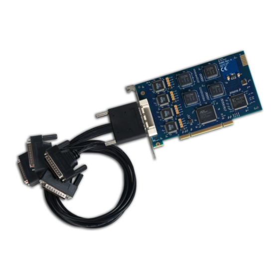
Introduction The ACB-MP+4.PCI (Item# 5402) is a four-port PCI bus RS-232, RS-422, RS-485 synchronous serial interface. Designed using the popular Zilog Z85230 Enhanced Serial Communication Controller (ESCC), the board is an ideal solution for military, satellite, radar, banking, and other applications that require robust synchronous communications. -
Page 4: Before You Get Started
Before You Get Started What’s Included The ACB-MP+4.PCI is shipped with the following items. If any of these items is missing or damaged please contact Sealevel for replacement. Item# 5402 – ACB-MP+4.PCI Adapter Item# CA339 – 100-Pin to (4) DB25M Breakout Cable, 36” in Length Item# SSI-CD –... -
Page 5: Installation & Configuration
XP, and Vista operating systems. 1. Start Windows. 2. Insert the Sealevel Systems CD in your CD drive. 3. If ‘Auto-Start’ is enabled for this drive the software will automatically launch. Otherwise launch the ‘autorun.exe’ file located in the root directory of the CD. -
Page 6: Physical Installation
5. Replace the screw (required for FCC Part 15 compliance). 6. Replace the cover. 7. Connect the power cord and power up the machine. The ACB-MP+4.PCI is now ready for use. © Sealevel Systems, Inc. - 4 - ACB-MP+4.PCI User Manual... -
Page 7: Technical Description
Technical Description The ACB-MP+4.PCI utilizes the Zilog 85230 Enhanced Serial Communications Controller (ESCC) and includes a dedicated Z85230 per port. This chip features programmable baud rate, data format and interrupt control. Refer to the ESCC Users Manual, available from Zilog, for details on programming the 85230 ESCC chip. -
Page 8: 100-Pin Connector Pin Out
100-Pin Connector Pin Out The ACB-MP+4.PCI has a 100-pin high-density connector and includes a cable (Item# CA339) that breaks out to four (4) DB25 male connectors. The pin outs for RS-232, RS-485, RS-530, RS-530A, and V.35 interfaces on the DB25 connectors are listed on the following pages. -
Page 9: Interface Selection
Interface Selection The ACB-MP+4.PCI supports a variety of electrical interfaces. Refer to the Control and Status Register Definitions found in the Technical Description section of this manual for this bit description. There is line termination on RXD, RXC, and TXC in the following modes: RS-530, RS-530A, RS-485T, and V.35. - Page 10 Data Terminal Ready Negative Output Remote Loopback Output DSRB DSR+ Data Set Ready Positive Input DTRB DTR+ Data Terminal Ready Positive Output TSETA TSET– Transmit Signal Element Timing – Output © Sealevel Systems, Inc. - 8 - ACB-MP+4.PCI User Manual...
- Page 11 Data Terminal Ready Output * Remote Loopback Output * TSETA TSET– Transmit Signal Element Timing – Output Note: All modem control signals are single ended (un-balanced) with RS-232 signal levels. © Sealevel Systems, Inc. - 9 - ACB-MP+4.PCI User Manual...
-
Page 12: Electrical Characteristics
10.69cm Manufacturing All Sealevel Systems Printed Circuit boards are built to UL 94V0 rating and are 100% electrically tested. These printed circuit boards are solder mask over bare copper with either Electroless Nickel Immersion Gold (ENIG) or Hot Air Solder Leveled (HASL) finish. -
Page 13: Appendix A - Troubleshooting
IRQ (if any) should be identified. 4. Configure your Sealevel Systems adapter so that there is no conflict with currently installed adapters. No two adapters can occupy the same I/O address. -
Page 14: Appendix B - How To Get Assistance
If possible, please have the adapter installed in a computer ready to run diagnostics. Sealevel Systems provides an FAQ section on its web site. Please refer to this to answer many common questions. This section can be found at http://www.sealevel.com/faq.asp... -
Page 15: Appendix C - Electrical Interface
(-3 to -10 volts) denotes a binary 1 (mark). The RS-232 and the EIA/TIA-574 specification defines two type of interface circuits, Data Terminal Equipment (DTE) and Data Circuit-Terminating Equipment (DCE). The Sealevel Systems adapter is a DTE interface. RS-422 The RS-422 specification defines the electrical characteristics of balanced voltage digital interface circuits. - Page 16 34 pin connector that supports 24 data, clock and control signals. The physical connector is defined in the ISO-2593 standard. ITU V.35 specification defines two type of interface circuits, Data Terminal Equipment (DTE) and Data Circuit-Terminating Equipment (DCE). The Sealevel Systems adapter is a DTE interface. © Sealevel Systems, Inc.
-
Page 17: Appendix D - Silk Screen - 5402 Pcb
Appendix D – Silk Screen – 5402 PCB © Sealevel Systems, Inc. - 15 - ACB-MP+4.PCI User Manual... -
Page 18: Appendix E - Compliance Notices
Always use cabling provided with this product if possible. If no cable is provided or if an alternate cable is required, use high quality shielded cabling to maintain compliance with FCC/EMC directives. © Sealevel Systems, Inc. - 16 - ACB-MP+4.PCI User Manual... -
Page 19: Warranty
(RMA) number. The Customer agrees to insure the Product or assume the risk of loss or damage in transit, to prepay shipping charges to Sealevel, and to use the original shipping container or equivalent. Warranty is valid only for original purchaser and is not transferable.
Need help?
Do you have a question about the ACB-MP+4.PCI and is the answer not in the manual?
Questions and answers