
Related Manuals for SeaLevel ULTRA COMM+2.LPCI


Summary of Contents for SeaLevel ULTRA COMM+2.LPCI
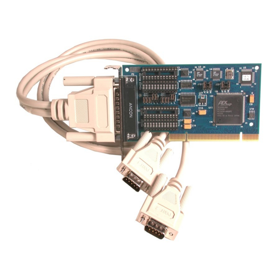
- Page 1 ULTRA COMM+2.LPCI User Manual | 7205 © Sealevel Systems, Inc. 7205 Manual | SL9062 10/2022...
-
Page 2: Table Of Contents
Appendix A – Troubleshooting Appendix B – How To Get Assistance Appendix C – Electrical Interface Appendix D – Asynchronous Communications Appendix E – Silk Screen Appendix F – Compliance Notices Warranty © Sealevel Systems, Inc. 7205 Manual | SL9062 10/2022... - Page 3 Introduction The Sealevel Systems ULTRACOMM+2.LPCI is a two channel Low Profile PCI serial I/O adapter for the PC and compatibles. It provides two field selectable RS232/422/485 serial ports supporting data rates up to 921.6K bps. Configure both ports as RS232 for standard serial COM: port requirements. Choose the RS-422 mode for long distance device connections up to 4000ft.
-
Page 4: Before You Get Started
Before You Get Started What’s Included The ULTRA COMM+2.LPCI is shipped with the following items. If any of these items are missing or damaged, contact the supplier. ULTRA COMM+2.LPCI Serial I/O Adapter • Item# 7205 ships with a Low Profile PCI bracket Item# 7205S ships with a standard size PCI bracket •... - Page 5 Port # Electrical Specification Port 1 RS-232 Port 2 RS-232 To install the ULTRA COMM+2.LPCI using factory default settings, refer to Installation. For your reference, record installed ULTRA 485+2.PCI settings below: Port # Electrical Specification Port 1 Port 2 © Sealevel Systems, Inc.
-
Page 6: Card Setup
Some communication software packages refer to RS-485 as RTS enable or RTS block mode transfer. One of the unique features of the ULTRA COMM+2.LPCI is the ability to be RS-485 compatible without the need for special software or drivers. This ability is especially useful in Windows, Windows NT, and OS/2 environments where the lower level I/O control is abstracted from the application program. - Page 7 Figure 3 - Headers J1B and J2B, RS-485 ‘Auto’ Enabled, with ‘Echo’ Figure 4 - Headers J1B and J2B, RS-485 ‘RTS’ Enabled, with ‘No Echo’ Figure 5 - Headers J1B and J2B, RS-485 ‘RTS’ Enabled, with ‘Echo’ © Sealevel Systems, Inc. 7205 Manual | SL9062 10/2022...
- Page 8 Each jumper position corresponds to a specific portion of the interface. If multiple ULTRA COMM+2.LPCI adapters are configured in a RS-485 network, only the boards on each end should have jumpers T, P & P ON. Refer to the following table for each position’s operation:...
- Page 9 Electrical Interface Selection Each port on the ULTRA COMM+2.LPCI has the ability to be used in either RS-232 or RS-422/485. This is selectable via four 24 pin DIP-shunts at E1-E4. Please use the following illustration to aid in the configuration of your electrical interface.
-
Page 10: Hardware Installation
7. The software is now installed, and you can proceed with the hardware installation. 8. Refer to the Physical Installation section to connect and install your adapter. All Sealevel Systems software drivers have been fully tested by Sealevel. Clicking ‘OK’ will not harm your system. - Page 11 For additional software support, including QNX, please call Sealevel Systems’ Technical Support, (864) 843- 4343. Our technical support is free and available from 8:00 AM - 5:00 PM Eastern Time, Monday through Friday. For email support contact: support@sealevel.com.
- Page 12 4. Gently insert the PCI adapter into the slot. Make sure that the adapter is seated properly. 5. Replace the screw. (This is required to ensure FCC Part 15 compliance.) 6. Replace the cover. 7. Connect the power cord Installation is finished. © Sealevel Systems, Inc. 7205 Manual | SL9062 10/2022...
-
Page 13: Technical Description
The ULTRA COMM+2.LPCI utilizes the 16850 UART. This chip features programmable baud rates, data format, interrupt control and a 128-byte input and output FIFO. The ULTRA COMM+2.LPCI also supports the Oxford Semiconductor 16C950. This chip features the same FIFO and automatic RS-485 driver enable capabilities as the 16C850, and enhanced clocking features. - Page 14 Input CTS+ Clear To Send Positive Input CTS- Clear To Send Negative Input DB-25M (Card Edge Connector) RS-232 RS-422/485 Port 1 Pin # Port 2 Pin # CTS- RTS- RTS+ CTS+ © Sealevel Systems, Inc. 7205 Manual | SL9062 10/2022...
- Page 15 The following table shows some common data rates and the rates you should choose to achieve them when using the ULTRA COMM+2.LPCI. If the O/S of choice is Windows 95/98/ME/2000/NT/XP, the oscillator value (14.7456 MHz) will be automatically entered into the ‘Advanced Tab’ on 95/98/Me/2000/XP Device Manager applet.
-
Page 16: Specifications
10 to 90% R.H. Non-Condensing Manufacturing All Sealevel Systems Printed Circuit boards are built to UL 94V0 rating and are 100% electrically tested. These printed circuit boards are solder mask over bare copper or solder mask over tin nickel. Power Consumption... -
Page 17: Appendix A - Troubleshooting
‘SSD’. 6. For Windows 95 and Windows NT, the diagnostic tool ‘WinSSD’ is installed in the Sealevel folder on the Start Menu during the setup process. First find the ports using the Device Manager, then use ‘WinSSD’... -
Page 18: Appendix B - How To Get Assistance
If possible, please have the adapter installed in a computer ready to run diagnostics. 3. Sealevel Systems provides an FAQ section on its web site. Please refer to this to answer many common questions. This section can be found at http://www.sealevel.com/faq.asp. -
Page 19: Appendix C - Electrical Interface
(Tx+ to Rx+ and Tx- to Rx-). Four wire mode allows full duplex data transfers. RS-485 does not define a connector pin-out or a set of modem control signals. RS-485 does not define a physical connector. © Sealevel Systems, Inc. 7205 Manual | SL9062 10/2022... -
Page 20: Appendix D - Asynchronous Communications
The communication parameters are baud rate, parity, number of data bits per character, and stop bits (i.e.9600,N,8,1). © Sealevel Systems, Inc. 7205 Manual | SL9062 10/2022... -
Page 21: Appendix E - Silk Screen
Appendix E – Silk Screen 2.536" 4.721" © Sealevel Systems, Inc. 7205 Manual | SL9062 10/2022... -
Page 22: Appendix F - Compliance Notices
Always use cabling provided with this product if possible. If no cable is provided or if an alternate cable is required, use high quality shielded cabling to maintain compliance with FCC/EMC directives. © Sealevel Systems, Inc. 7205 Manual | SL9062 10/2022... -
Page 23: Warranty
Sealevel's commitment to providing the best I/O solutions is reflected in the Lifetime Warranty that is standard on all Sealevel manufactured I/O products. We are able to offer this warranty due to our control of manufacturing quality and the historically high reliability of our products in the field. Sealevel products are designed and manufactured at its Liberty, South Carolina facility, allowing direct control over product development, production, burn-in and testing.
Need help?
Do you have a question about the ULTRA COMM+2.LPCI and is the answer not in the manual?
Questions and answers