
Related Manuals for SeaLevel ULTRA 530.LPCI


Summary of Contents for SeaLevel ULTRA 530.LPCI
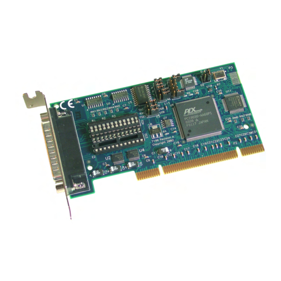
- Page 1 ULTRA 530.LPCI User Manual Part Number 7106 www.sealevel.com PO Box 830 Liberty, SC 29657 864.843.4343...
-
Page 2: Table Of Contents
APPENDIX D – ASYNCHRONOUS COMMUNICATIONS .............. 18 APPENDIX E – SILK SCREEN – 7106 PCB..................19 APPENDIX F - COMPLIANCE NOTICES ..................20 ............20 EDERAL OMMUNICATIONS OMMISSION TATEMENT WARRANTY............................. 21 © Sealevel Systems, Inc. ULTRA 530.LPCI User Manual SL9054 Revision 7/2006... -
Page 3: Introduction
COM: driver to be utilized for RS-485 communications. Our on- board hardware automatically handles the RS-485 driver enable. The ULTRA 530.LPCI ships with a Low Profile PCI bracket that will only work in a Low Profile PCI slot. If you need a standard size PCI bracket, please order Item# 7106S. -
Page 4: Before You Get Started
Before You Get Started What’s Included The ULTRA 530.LPCI is shipped with the following items. If any of these items is missing or damaged please contact Sealevel for replacement. ULTRA 530.LPCI Adapter Sealevel SeaI/O Software CD Optional Items Depending upon your application, you are likely to find one or more of the following items useful for interfacing the ULTRA 530.LPCI to real-world signals. -
Page 5: Card Setup
Some communication software packages refer to RS-485 as RTS enable or RTS block mode transfer. One of the unique features of the ULTRA 530.LPCI is the ability to be RS-485 compatible without the need for special software or drivers. This ability is especially useful in Windows, Windows NT, and OS/2 environments where the lower level I/O control is abstracted from the application program. -
Page 6: Rs-485 Mode Examples (Header E5)
Figure 3 - Header E5, RS-485 ‘Auto’ Enabled, with ‘Echo’ Figure 4 - Header E5, RS-485 ‘RTS’ Enabled, with ‘No Echo’ Figure 5 – Header E5, RS-485 ‘RTS’ Enabled, with ‘Echo’ ULTRA 530.LPCI User Manual © Sealevel Systems, Inc. - 4 -... -
Page 7: Address And Irq Selection
Figure 6 – Header E5, RS-485 ‘DTR’ Enabled, with No Echo Address and IRQ selection The ULTRA 530.LPCI is automatically assigned I/O addresses and IRQs by your motherboard BIOS. Only the I/O address may be modified by the user. Adding or removing other hardware may change the assignment of I/O addresses and IRQs. -
Page 8: Electrical Interface Selection
Electrical Interface Selection Each port on the ULTRA 530.LPCI has the ability to be used in either RS-232 or RS-422/485. This is selectable via two 24 pin DIP-shunts at E1and E2. Please use the following illustration to aid in the configuration of your electrical interface. -
Page 9: Clock Modes
Clock Modes The ULTRA 530.LPCI employs a unique clocking option that allows the end user to select from divide by 8 and divide by 1 clocking modes. These modes are selected at Header E6. To select the Baud rates commonly associated with COM: ports (i.e. 2400, 4800, 9600, 19.2, …... -
Page 10: Baud Rates And Divisors For The 'Div1' Mode
Technical Description section). The header that provides the selection of either a modem control signal or the clock option is header E3. Figure 12 - Header E3, Clocking and Modem control signal selection ULTRA 530.LPCI User Manual © Sealevel Systems, Inc. - 8 -... -
Page 11: Software Installation
Windows 98/ME/2000/XP Installation 1. Start Windows. 2. Insert the Sealevel Systems CD in to your CD drive. 3. If ‘Auto-Start’ is enabled for this drive the software will automatically launch. Otherwise, point your browser to the ‘Index.htm’ on the root directory of the CD 4. -
Page 12: Linux Installation
Skip to section "Using the test software" if you wish to do so at this time. To set up Linux to automatically load the driver; refer to a Linux manual concerning your specific distribution for help. ULTRA 530.LPCI User Manual © Sealevel Systems, Inc. - 10 -... -
Page 13: Physical Installation
(This is required to ensure FCC Part 15 compliance.) 7. Replace the cover. 8. Connect the power cord The ULTRA 530.LPCI is now ready for use. ULTRA 530.LPCI User Manual © Sealevel Systems, Inc. - 11 -... -
Page 14: Technical Description
Technical Description The Sealevel Systems ULTRA 530.LPCI provides a PCI interface adapter with an additional asynchronous serial port providing a versatile interface, field selectable as RS-232 for modems, printers and plotters, as well as RS-422/485/530 for industrial automation and control applications. - Page 15 Note: These assignments meet the EIA/TIA/ANSI-530 DTE specification with the exception of Ring Indicator, which is not specified. It has been included here for compatibility with systems requiring Ring Indicator. ULTRA 530.LPCI User Manual © Sealevel Systems, Inc. - 13 -...
-
Page 16: Electrical Characteristics
2.5” (6.4 cm, including Gold fingers) Manufacturing All Sealevel Systems Printed Circuit boards are built to UL 94V0 rating and are 100% electrically tested. These printed circuit boards are solder mask over bare copper or solder mask over tin nickel. -
Page 17: Appendix A - Troubleshooting
4. Configure your Sealevel Systems adapter so that there is no conflict with currently installed adapters. No two adapters can occupy the same I/O address. 5. Make sure the Sealevel Systems adapter is using a unique IRQ. While the Sealevel Systems adapter does allow the sharing of IRQs, many other adapters (i.e. -
Page 18: Appendix B - How To Get Assistance
If possible, please have the adapter installed in a computer ready to run diagnostics. Sealevel Systems provides an FAQ section on its web site. Please refer to this to answer many common questions. This section can be found at http://www.sealevel.com/faq.asp... -
Page 19: Appendix C - Electrical Interface
The RS-530 specification defines two types of interface circuits, Data Terminal Equipment (DTE) and Data Circuit-Terminating Equipment (DCE). The Sealevel Systems adapter is a DTE interface. ULTRA 530.LPCI User Manual © Sealevel Systems, Inc. -
Page 20: Appendix D - Asynchronous Communications
The communication parameters are baud rate, parity, number of data bits per character, and stop bits (i.e. 9600, N, 8, 1). ULTRA 530.LPCI User Manual © Sealevel Systems, Inc. - 18 -... -
Page 21: Appendix E - Silk Screen - 7106 Pcb
Appendix E – Silk Screen – 7106 PCB 2.536" 4.721" ULTRA 530.LPCI User Manual © Sealevel Systems, Inc. - 19 -... -
Page 22: Appendix F - Compliance Notices
Always use cabling provided with this product if possible. If no cable is provided or if an alternate cable is required, use high quality shielded cabling to maintain compliance with FCC/EMC directives. ULTRA 530.LPCI User Manual © Sealevel Systems, Inc. - 20 -... -
Page 23: Warranty
(RMA) number. The Customer agrees to insure the Product or assume the risk of loss or damage in transit, to prepay shipping charges to Sealevel, and to use the original shipping container or equivalent. Warranty is valid only for original purchaser and is not transferable.
Need help?
Do you have a question about the ULTRA 530.LPCI and is the answer not in the manual?
Questions and answers