
Related Manuals for SeaLevel ULTRA COMM+422.PCI


Summary of Contents for SeaLevel ULTRA COMM+422.PCI
- Page 1 ULTRA COMM+422.PCI User Manual | 7402 © Sealevel Systems, Inc. 7402 Manual | SL9063 7/2021...
-
Page 2: Table Of Contents
APPENDIX C – ASYNCHRONOUS COMMUNICATIONS ............................. 22 APPENDIX D – CAD DRAWING ...................................... 23 APPENDIX E – HOW TO GET ASSISTANCE .................................. 24 APPENDIX F – COMPLIANCE NOTICES..................................25 WARRANTY ............................................26 © Sealevel Systems, Inc. 7402 Manual | SL9063 7/2021... -
Page 3: Safety Instructions
Keep work area free of non-conductive materials such as ordinary plastic assembly aids and Styrofoam. • Use field service tools such as cutters, screwdrivers, and vacuum cleaners which are conductive. • Always place drives and boards PCB-assembly-side down on the foam. © Sealevel Systems, Inc. 7402 Manual | SL9063 7/2021... -
Page 4: Introduction
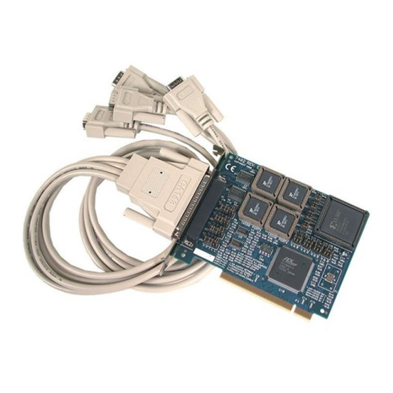
Introduction The Sealevel ULTRA COMM+422.PCI is a four channel PCI Bus serial I/O adapter for the PC and compatibles supporting data rates up to 460.8K bps. RS-422 provides excellent communications for long distance device connections up to 4000ft., where noise immunity and high data integrity are essential. -
Page 5: Before You Get Started
Before You Get Started What’s Included The ULTRA COMM+422.PCI is shipped with the following items. If any of these items are missing or damaged, please contact Sealevel for replacement. • ULTRA COMM+422.PCI Serial I/O Adaptar • Spider Cable providing 4 DB-9 connectors... - Page 6 Optional Items Depending upon your application, you are likely to find one or more of the following items useful with the ULTRA COMM+422.PCI. All items can be purchased from our website (www.sealevel.com) by calling our sales team at (864) 843-4343.
- Page 7 DB9M connector. DB9 Female (RS-422) to DB9 Female (Opto 22 Optomux) Converter (Item# DB103) The DB103 is designed to convert a Sealevel DB9 male RS-422 connector to a DB9 female pinout compatible with AC24AT and AC422AT Opto 22 ISA bus cards. This allows Optomux devices to be controlled from any Sealevel RS-422 board with a DB9 male connector.
- Page 8 Auto Port 3 Auto Port 4 Auto To install the ULTRA COMM+422.PCI using factory default settings, refer to Installation on page 9. For your reference, record installed ULTRA COMM+422.PCI settings below: Port # Clock DIV Mode Enable Mode Port 1...
-
Page 9: Card Setup
Some communication software packages refer to RS-485 as RTS enable or RTS block mode transfer. One of the unique features of the ULTRA COMM+422.PCI is the ability to be RS-485 compatible without the need for special software or drivers. This ability is especially useful in Windows, Windows NT, and OS/2 environments where the lower level I/O control is abstracted from the application program. - Page 10 Figure 3 - Headers J1B – J4B, RS-485 ‘Auto’ Enabled, with ‘Echo’ Figure 4 - Headers J1B – J4B, RS-485 ‘RTS’ Enabled, with ‘No Echo’ Figure 5 - Headers J1B – J4B, RS-485 ‘RTS’ Enabled, with ‘Echo’ © Sealevel Systems, Inc. 7402 Manual | SL9063 7/2021...
- Page 11 Each jumper position corresponds to a specific portion of the interface. If multiple ULTRA COMM+422.PCI adapters are configured in an RS-485 network, only the boards on each end should have jumpers T, P & P ON. Refer to the following table for each position’s operation:...
- Page 12 Clock Modes The ULTRA COMM+422.PCI employs a unique clocking option that allows the end user to select from divide by 4, divide by 2 and divide by 1 clocking modes. These modes are selected at Headers J1C through J4C. To select the Baud rates commonly associated with COM: ports (i.e., 2400, 4800, 9600, 19.2, … 115.2K Bps) place the jumper in the divide by 4 mode (silk-screen DIV4).
- Page 13 If your communications package allows the use of Baud rate divisors, choose the appropriate divisor from the following table: For this Data Rate Choose this Divisor 1200 bps 2400 bps 4800 bps 9600 bps 19.2K bps 38.4K bps 57.6K bps 115.2K bps 230.4K bps 460.8K bps © Sealevel Systems, Inc. 7402 Manual | SL9063 7/2021...
- Page 14 If your communications package allows the use of Baud rate divisors, choose the appropriate divisor from the following table: For this Data Rate Choose this Divisor 1200 bps 2400 bps 4800 bps 9600 bps 19.2K bps 38.4K bps 57.6K bps 115.2K bps 230.4K bps © Sealevel Systems, Inc. 7402 Manual | SL9063 7/2021...
-
Page 15: Installation
Only users running Windows 7 or newer should utilize these instructions for accessing and installing the appropriate driver via Sealevel’s website. If you are utilizing an operating system prior to Windows 7, please contact Sealevel by calling 864.843.4343 or emailing support@sealevel.com... - Page 16 For additional software support, including QNX, please call Sealevel Systems’ Technical Support, (864) 843- 4343. Our technical support is free and available from 8:00 AM - 5:00 PM Eastern Time, Monday through Friday. For email support contact: support@sealevel.com.
-
Page 17: Technical Description
IRQ (short for Interrupt Request). In the early days of PCs Sealevel decided that the ability to share IRQs was an important feature for any add-in I/O card. Consider that in the IBM XT the available IRQs were IRQ0 through IRQ7. Of these interrupts only IRQ2-5 and IRQ7 were actually available for use. - Page 18 COMM+422.PCI will allow any one of the available locations to be read to obtain the value in the status register. Both status ports on the ULTRA COMM+422.PCI are identical, so any one can be read. Example: This indicates that Channel 2 has an interrupt pending.
-
Page 19: Product Overview
10 to 90% R.H. Non-Condensing Manufacturing All Sealevel Systems Printed Circuit boards are built to UL 94V0 rating and are 100% electrically tested. These printed circuit boards are solder mask over bare copper or solder mask over tin nickel. Power Consumption... -
Page 20: Appendix A - Troubleshooting
No two adapters can occupy the same I/O address. Make sure the Sealevel Systems adapter is using a unique IRQ The IRQ is typically selected via an on-board header block. Refer to the section on Card Setup for help in choosing an I/O address and IRQ. -
Page 21: Appendix B - Electrical Interface
(Tx+ to Rx+ and Tx- to Rx-). Four wire mode allows full duplex data transfers. RS-485 does not define a connector pin-out or a set of modem control signals. RS-485 does not define a physical connector. © Sealevel Systems, Inc. 7402 Manual | SL9063 7/2021... -
Page 22: Appendix C - Asynchronous Communications
The communication parameters are baud rate, parity, number of data bits per character, and stop bits (i.e., 9600,N,8,1). © Sealevel Systems, Inc. 7402 Manual | SL9063 7/2021... -
Page 23: Appendix D - Cad Drawing
Appendix D – CAD Drawing 4.2" 5.2" © Sealevel Systems, Inc. 7402 Manual | SL9063 7/2021... -
Page 24: Appendix E - How To Get Assistance
If possible, please have the adapter installed in a computer ready to run diagnostics. 3. Sealevel Systems provides an FAQ section on its web site. Please refer to this to answer many common questions. This section can be found at http://www.sealevel.com/faq.htm... -
Page 25: Appendix F - Compliance Notices
Always use cabling provided with this product if possible. If no cable is provided or if an alternate cable is required, use high quality shielded cabling to maintain compliance with FCC/EMC directives. © Sealevel Systems, Inc. 7402 Manual | SL9063 7/2021... -
Page 26: Warranty
Sealevel's commitment to providing the best I/O solutions is reflected in the Lifetime Warranty that is standard on all Sealevel manufactured I/O products. We are able to offer this warranty due to our control of manufacturing quality and the historically high reliability of our products in the field. Sealevel products are designed and manufactured at its Liberty, South Carolina facility, allowing direct control over product development, production, burn-in and testing.
Need help?
Do you have a question about the ULTRA COMM+422.PCI and is the answer not in the manual?
Questions and answers