
Related Manuals for SeaLevel Ultra COMM+8.PCI


Summary of Contents for SeaLevel Ultra COMM+8.PCI
- Page 1 Ultra COMM+8.PCI User Manual | 7804c © Sealevel Systems, Inc. 7804c Manual | SL9716 03/2024...
-
Page 2: Table Of Contents
APPENDIX F – MECHANICAL DRAWING ..................................37 APPENDIX G – 7804 VERSUS 7804C ..................................38 APPENDIX H – PCIE NATIVE CONTROL..................................39 APPENDIX I - COMPLIANCE NOTICES ..................................40 WARRANTY ............................................41 © Sealevel Systems, Inc. 7804c Manual | SL9716 03/2024... -
Page 3: Introduction
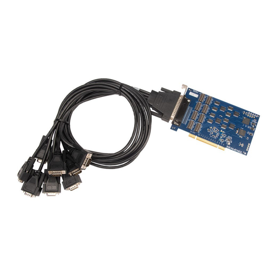
Introduction The Sealevel Ultra COMM+8.PCI (Item# 7804c) is a PCI compliant interface adapter with eight field selectable RS-232/422/485 asynchronous serial ports from a single PCI slot supporting data rates exceeding 1 Mbps for industrial automation and control applications. Configure the serial ports as RS232 for standard serial COM port requirements. Choose the RS-422 mode for long distance device connections up to 4000ft. -
Page 4: Before You Get Started
Before You Get Started What’s Included The Ultra COMM+8.PCI is shipped with the following items. If any of these items are missing or damaged, please contact Sealevel for replacement. Ultra COMM+8.PCI Adapter • 7804c – Eight Port Asynchronous Serial PCI Card •... - Page 5 Optional Items Depending upon your application, you are likely to find one or more of the following items useful with the 7804c. All items can be purchased from our website (www.sealevel.com) by calling our sales team at (864) 843-4343. RS-422 to RS-530 Cable (Part Number CA176) DB9 Female (RS-422) to DB25 Male (RS-530) Cable, 10 inch Length.
- Page 6 Terminal Block Kit (Part Number KT106) The TB06 terminal block has been designed to connect directly to any Sealevel dual DB9 serial board or to serial boards with DB9 cables. If you need to extend the length of your dual DB9 connection, the KT106 includes the TB06 terminal block and two CA127 DB9 extension cables.
-
Page 7: Card Setup
DIP switches. Please use the following examples to configure your adapter. Mode selection via hardware (DIP switches) M1 Switch M0 Switch Mode RS-232 RS-422 (Default) RS-485 with Echo RS-485 without Echo © Sealevel Systems, Inc. 7804c Manual | SL9716 03/2024... - Page 8 Enables RS-422/RS-485 RX+ 1K ohm pull-up to 3.3V (biasing) Enables RS-422/RS-485RX– 1K ohm pull-down to GND (biasing) Enables RS-485 two-wire mode, connecting TX– to RX– Enables RS-485 two-wire mode, connecting TX+ to RX+ © Sealevel Systems, Inc. 7804c Manual | SL9716 03/2024...
- Page 9 The 7804c supports selection of RS232, RS422, and RS485 electrical modes via hardware dip switches. Refer to the images below for common configurations. Figure 1 - RS-232 Mode Figure 2 - RS-422 Mode Figure 3 - RS-485 with 'Echo' Figure 4 - RS-485 No 'Echo' © Sealevel Systems, Inc. 7804c Manual | SL9716 03/2024...
- Page 10 RS485 Aware Application Control Notes (SER_RS485_ENABLED) Signal 6.7+ 5.15.49 – 6.6X Auto RS485 not supported by the kernel Below Not Supported driver prior to 5.15.149. Please contact 5.15.149 Sealevel Tech Support for assistance. © Sealevel Systems, Inc. 7804c Manual | SL9716 03/2024...
- Page 11 RTS/DTR Use DTR as the RS485 direction control signal AUTO switch is ignored on Linux unless a kernel patch is applied. Contact Sealevel Tech Support for details. . RTS/DTR switch needs to match the current UART direction control configuration. Refer to RS- 485 Enable Modes”...
- Page 12 This is the default configuration for SW1 on the 7804c. Figure 7: Auto-RS485 is ENABLED and RTS is selected as the RS-485 direction control signal Figure 8: Auto-RS485 is ENABLED and DTR is selected as the RS-485 direction control signal © Sealevel Systems, Inc. 7804c Manual | SL9716 03/2024...
- Page 13 RTS/DTR changes from LOW to HIGH when a data byte is loaded into the THR or transmit FIFO. • The change to HIGH occurs prior to sending the start-bit. SW1; AUTO switch is ignored on Linux unless a kernel patch is applied. Contact Sealevel Tech Support for details. SW1; AUTO must be configured prior to power-up.
- Page 14 UART in different scenarios. SW1; RTS/DTR Control Signal Signal Level Transmitter De-asserted (Logic High) Active Asserted (Logic Low) Tri-Stated De-asserted (Logic High) Tri-Stated Asserted (Logic Low) Active © Sealevel Systems, Inc. 7804c Manual | SL9716 03/2024...
- Page 15 0 to 15 bit-time delay that is inserted after the end of the last stop-bit of the last transmitted character. This delay controls when to automatically disable the RS-485 transmitter. This delay may be useful in long-cable networks. © Sealevel Systems, Inc. 7804c Manual | SL9716 03/2024...
- Page 16 LED States Defined: ON = Solidly Lit ii) OFF = Completely Off iii) Slow Flash = 1 sec on / 1 sec off Fast Flash = 250mS on / 250mS off © Sealevel Systems, Inc. 7804c Manual | SL9716 03/2024...
-
Page 17: Technical Description
Technical Description The Sealevel Systems 7804c provides a PCI interface adapter with eight (8) asynchronous serial ports providing versatile, field selectable RS-232 interfaces for modems, printers, and plotters, as well as RS- 422/485 interfaces for industrial automation and control applications. - Page 18 Port 5 RX– (I) Port 1 DCD Port 1 RX+ (I) Port 5 DCD Port 5 RX+ (I) “N/C” = Not Connected (unused) “–” = Reserved (I) = Input (O) = Output © Sealevel Systems, Inc. 7804c Manual | SL9716 03/2024...
- Page 19 RTS to CTS and RI, and to connect DTR to DCD and DSR. In RS-422/485 mode connect RTS+ to CTS+ and RTS– to CTS–. Terminating these pins, if not used, will help ensure the best performance from the adapter. © Sealevel Systems, Inc. 7804c Manual | SL9716 03/2024...
-
Page 20: Technical Specifications
At 25º C ambient Manufacturing All Sealevel Systems Printed Circuit boards are built to UL 94V0 rating and are 100% electrically tested. These printed circuit boards are solder mask over bare copper or solder mask over tin nickel. Power Consumption Supply Voltage +3.3 VDC... -
Page 21: Software Installation
Windows and Linux operating systems. Where to Get Software Current versions of Sealevel software packages can be obtained from the Sealevel website. If you already have all the required software, proceed to the installation section for your operating system. - Page 22 3. Once opened Select ‘Next’ as demonstrated in the image below. 4. When the ‘License Agreement’ window appears, accept the terms, and click ‘Next’ to continue. If you do not accept the terms of the agreement, the wizard will stop. © Sealevel Systems, Inc. 7804c Manual | SL9716 03/2024...
- Page 23 Click on the button to continue installation of your Sealevel software. The below warning will appear when installing the driver on Windows 7. Select “Install this driver anyway”...
- Page 24 6. Click ‘Finish’ to complete the installation of SeaCOM onto your PC. 7. If prompted, reboot your computer for changes to take effect. © Sealevel Systems, Inc. 7804c Manual | SL9716 03/2024...
- Page 25 For additional software support or if you have any questions about using the 7803c in your system, please call Sealevel Systems’ Technical Support, (864) 843-4343. Our technical support is free and available from 8:00 AM - 5:00 PM Eastern Time, Monday through Friday. For email support contact: support@sealevel.com.
-
Page 26: Hardware Installation
= 7812500) is a XR17V35X 1.295751] 0000:01:00.0: ttyS6 at MMIO 0xf5cfd800 (irq = 24, base_baud = 7812500) is a XR17V35X 1.295840] 0000:01:00.0: ttyS7 at MMIO 0xf5cfdc00 (irq = 24, base_baud = 7812500) is a XR17V35X © Sealevel Systems, Inc. 7804c Manual | SL9716 03/2024... - Page 27 &LPT)’ and in parentheses should be a COM number assigned to each port number. Your system will assign the next available COM number, which will vary by computer (COM1 through COM8 are shown in this example). © Sealevel Systems, Inc. 7804c Manual | SL9716 03/2024...
- Page 28 If you want to completely remove the hardware and software from your computer, power down your computer, remove the device from the PCI slot, and then reboot your computer to complete the uninstallation. © Sealevel Systems, Inc. 7804c Manual | SL9716 03/2024...
-
Page 29: Appendix A - Troubleshooting
Appendix A – Troubleshooting Once you have confirmed that the serial adapter COM ports are listed in Device Manager, use the Sealevel WinSSD utility to verify communications. Detailed help is included in the WinSSD utility. Please set the adapters Electrical Interface for either RS-232 or RS-422. - Page 30 Change your parameters to 9600 bits per second, 8 data bits, no parity, 1 stop bit, and no flow control, as pictured below. Click ‘Apply’ and ‘OK’. In the main WinSSD window, click on the ‘BERT’ tab (Bit Error Rate test). Click on the ‘Start’ button. © Sealevel Systems, Inc. 7804c Manual | SL9716 03/2024...
- Page 31 If these steps do not solve your problem, please call Sealevel Systems’ Technical Support, (864) 843-4343. Our technical support is free and available from 8:00 A.M.- 5:00 P.M. Eastern Time Monday through Friday.
-
Page 32: Appendix B - Handling Instructions
Keep the work area free of non-conductive materials such as ordinary plastic assembly aids and • Styrofoam. Use field service tools such as cutters, screwdrivers, and vacuum cleaners that are conductive. • © Sealevel Systems, Inc. 7804c Manual | SL9716 03/2024... -
Page 33: Appendix C - Electrical Interface
+10 volts) represents a binary 0 (space) and -12 volts (-3 to -10 volts) denote a binary 1 (mark). The RS-232 and the EIA/TIA-574 specification define two types of interface circuits Data Terminal Equipment (DTE) and Data Circuit-Terminating Equipment (DCE). The Sealevel Systems Adapter is a DTE interface. RS-422 The RS-422 specification defines the electrical characteristics of balanced voltage digital interface circuits. - Page 34 (Tx+ to Rx+ and Tx- to Rx-). Four wire mode allows full duplex data transfers. RS-485 does not define a connector pin-out or a set of modem control signals. RS-485 does not define a physical connector. © Sealevel Systems, Inc. 7804c Manual | SL9716 03/2024...
-
Page 35: Appendix D - Asynchronous Communications
The communication parameters are baud rate, parity, number of data bits per character, and stop bits (i.e., 9600,N,8,1). © Sealevel Systems, Inc. 7804c Manual | SL9716 03/2024... -
Page 36: Appendix E - Ground Loop Phenomenon
DC to DC converter circuit or in the opto- isolator circuit. This condition will cause data errors and possibly destruction of the receiver circuit. DATA+ DATA- Isolated Isolated Adapter Ground Adapter Isolation Barrier © Sealevel Systems, Inc. 7804c Manual | SL9716 03/2024... -
Page 37: Appendix F - Mechanical Drawing
Appendix F – Mechanical Drawing © Sealevel Systems, Inc. 7804c Manual | SL9716 03/2024... -
Page 38: Appendix G - 7804 Versus 7804C
Manual (DIV1/DIV4 Jumper) Automatic Max Baud Rate Up to 460.8 Kbps 1 Mbps or more Interrupt Status Port (ISP) Register Space Port Mapped Memory Mapped Minimum OS Required Windows XP Windows 7 © Sealevel Systems, Inc. 7804c Manual | SL9716 03/2024... -
Page 39: Appendix H - Pcie Native Control
1. Open a Windows command prompt as an administrator. 2. Enter the command: bcdedit /set {current} pciexpress forcedisable 3. Restart the computer. 4. You may revert the change by running the command: bcdedit /set {current} pciexpress default © Sealevel Systems, Inc. 7804c Manual | SL9716 03/2024... -
Page 40: Appendix I - Compliance Notices
Always use the cabling provided with this product if possible. If no cable is provided or if an alternate cable is required, use high quality shielded cabling to maintain compliance with FCC/EMC directives. © Sealevel Systems, Inc. 7804c Manual | SL9716 03/2024... -
Page 41: Warranty
Sealevel's commitment to providing the best I/O solutions is reflected in the Lifetime Warranty that is standard on all Sealevel manufactured I/O products. We are able to offer this warranty due to our control of manufacturing quality and the historically high reliability of our products in the field. Sealevel products are designed and manufactured at its Liberty, South Carolina facility, allowing direct control over product development, production, burn-in and testing.
Need help?
Do you have a question about the Ultra COMM+8.PCI and is the answer not in the manual?
Questions and answers