
Related Manuals for Moxa Technologies EtherDevice EDS-405A/408A Series


Summary of Contents for Moxa Technologies EtherDevice EDS-405A/408A Series
- Page 1 EDS-405A/408A Series Hardware Installation Guide Moxa EtherDevice™ Switch Eighth Edition, November 2010 2010 Moxa Inc. All rights reserved. Reproduction without permission is prohibited. P/N: 1802004000017...
-
Page 2: Package Checklist
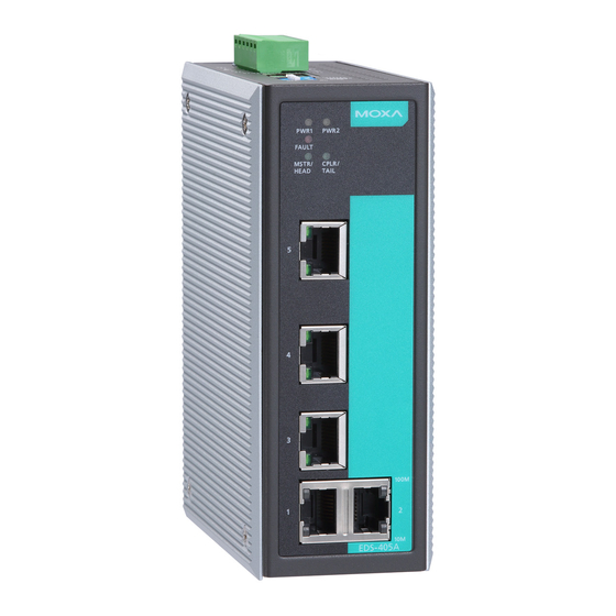
Overview The Moxa EtherDevice™ EDS-405A/408A series, which includes both 5 and 8-port smart Ethernet switches, is a cost-effective solution for your Ethernet connections. In addition, the built-in smart alarm function helps system maintainers monitor the health of your Ethernet network. Package Checklist The Moxa EDS-405A/408A switches are shipped with the following items. - Page 3 EDS-405A/408A Panel Layout (standard) Grounding screw Terminal block for power input PWR1/PWR2 and relay output Heat dissipation vents Console port DIP switches Power input PWR1 LED Power input PWR2 LED Fault LED MSTR/HEAD: LED indicator CPLR/TAIL: LED indicator Turbo Chain logo TP port’s 100 Mbps LED TP port’s 10 Mbps LED Model Name...
- Page 4 EDS-405A/408A-MM (SC-type) Panel Layout NOTE: The appearance of the EDS-405A-SS-SC is identical to that of the EDS-405A-MM-SC. The appearance of the EDS-408A-SS-SC is identical to that of the EDS-408A-MM-SC. Grounding screw Terminal block for power input PWR1/PWR2 and relay output Heat dissipation vents Console port DIP switches...
- Page 5 EDS-405A/408A-MM (ST-type) Panel Layout Grounding screw Terminal block for power input PWR1/PWR2 and relay output Heat dissipation vents Console port DIP switches Power input PWR1 LED Power input PWR2 LED Fault LED MSTR/HEAD: LED indicator CPLR/TAIL: LED indicator Turbo Chain logo TP port’s 100 Mbps LED TP port’s 10 Mbps LED Model Name...
-
Page 6: Eds-408A-3M Panel Layout (Sc/St-Type)
EDS-408A-3M Panel Layout (SC/ST-type) NOTE: The appearance of the EDS-408A-3S-SC, EDS-408A-1M2S-SC, and EDS-408A-2M1S-SC are identical to that of the EDS-408A-3M-SC. Grounding screw Terminal block for power input PWR1/PWR2 and relay output Console port DIP switches Heat dissipation vents Power input PWR1 LED Power input PWR2 LED Fault LED MSTR/HEAD: LED indicator... -
Page 7: Mounting Dimensions (Unit = Mm)
Mounting Dimensions (unit = mm) DIN-Rail Mounting The aluminum DIN-Rail attachment plate should already be fixed to the back panel of the EDS-405A/408A when you take it out of the box. If you need to reattach the DIN-Rail attachment plate, make sure the stiff metal spring is situated towards the top, as shown in the following figures. -
Page 8: Wall Mounting (Optional)
Wall Mounting (optional) For some applications, you will find it convenient to mount the EDS-405A/408A on the wall, as shown in the following figures. STEP 1: Remove the aluminum DIN-Rail attachment plate from the EDS-405A/408A’s ⇒ rear panel, and then attach the wall mount plates with M3 screws, as shown in the diagram at the right. -
Page 9: Wiring Requirements
Wiring Requirements WARNING Safety First! Be sure to disconnect the power cord before installing and/or wiring your Moxa EtherDevice Switch. Calculate the maximum possible current in each power wire and common wire. Observe all electrical codes dictating the maximum current allowable for each wire size. If the current goes above the maximum ratings, the wiring could overheat, causing serious damage to your equipment. -
Page 10: Wiring The Redundant Power Inputs
A relay warning event is triggered. The EDS-405A/408A is the Master of this Turbo Ring, and the Turbo Ring is broken. There is a start-up failure. If none of these three conditions is satisfied, the fault circuit will remain closed. Wiring the Redundant Power Inputs The top two contacts and the bottom two contacts of the 6-contact terminal block connector on the EDS-405A/408A’s top panel are used for... -
Page 11: Rj45 (8-Pin) To Rj45 (8-Pin) Cross-Over Cable Wiring
MDI Port Pinouts MDI-X Port Pinouts 8-pin RJ45 Signal Signal RJ45 (8-pin) to RJ45 (8-pin) Straight-through Cable Wiring RJ45 (8-pin) to RJ45 (8-pin) Cross-over Cable Wiring 100BaseFX Ethernet Port Connection The concept behind the SC/ST port and cable is quite straightforward. Suppose you are connecting devices I and II;... -
Page 12: Redundant Power Inputs
ST-Port Pinouts ST-Port to ST-Port Cable Wiring ATTENTION This is a Class 1 Laser/LED product. To avoid causing serious damage to your eyes, do not stare directly into the laser beam. Redundant Power Inputs Both power inputs can be connected simultaneously to live DC power sources. -
Page 13: Led Indicators
EDS-405A/408A Series DIP Switches The default setting for each DIP Switch is OFF. The following table explains the effect of setting the DIP Switch to the ON position. “Turbo Ring” DIP Switch Settings DIP 1 DIP 2 DIP 3 DIP 4 Reserved for ON: Enables this ON: Enables the... -
Page 14: Auto Mdi/Mdi-X Connection
PWR2 AMBER Power is being supplied to power input PWR2. Power is not being supplied to power input PWR2. FAULT When (1) a relay warning event is triggered, (2) the EDS-405A/408A is the Master of this Turbo Ring, and the Turbo Ring is broken, or (3) start-up failure. -
Page 15: Specifications
Specifications Technology Standards IEEE802.3, 802.3u, 802.3x, 802.1D, 802.1Q, 802.1w, 802.1p Protocols IGMP V1/V2 device, GMRP, GVRP, SNMPv1/v2c/v3, DHCP Server/Client, TFTP, SNTP, SMTP, RARP, RMON, HTTP, Telnet, Syslog, DHCP Option 66/67/82, BootP, LLDP, Modbus TCP, IPv6 MIB-II, Ethernet-Like MIB, P-BRIDGE MIB, RMON MIB Group 1, 2, 3, 9, Bridge MIB, RSTP MIB Forwarding and 148810 pps... - Page 16 Physical Characteristics Housing Metal, IP30 protected Dimensions 53.6 × 135 × 105 mm Weight 0.65 kg (EDS-405A models) 0.89 kg (EDS-408A models) Installation DIN-Rail, Wall Mounting (optional kit) Environmental Limits Operating Temperature 0 to 60°C (32 to 140°F); -40 to 75°C (-40 to 167°F ) for -T models Storage Temperature -40 to 85°C (-40 to 185°F) Ambient Relative Humidity 5% to 95% (non-condensing)
Need help?
Do you have a question about the EtherDevice EDS-405A/408A Series and is the answer not in the manual?
Questions and answers