Moxa Technologies EDS-405A Series Quick Installation Manual
Hide thumbs
Also See for EDS-405A Series:
- User manual (103 pages) ,
- Hardware installation manual (18 pages) ,
- Manual (84 pages)
Table of Contents

Related Manuals for Moxa Technologies EDS-405A Series


Summary of Contents for Moxa Technologies EDS-405A Series
- Page 1 EDS-405A/408A Series Quick Installation Guide Moxa EtherDevice™ Switch Version 12.4, June 2022 Technical Support Contact Information www.moxa.com/support 2022 Moxa Inc. All rights reserved. P/N: 1802004000079 *1802004000079*...
-
Page 2: Package Checklist
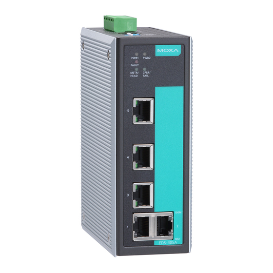
Overview The Moxa EtherDevice™ EDS-405A/408A series, which includes both 5 and 8-port smart Ethernet switches, is a cost-effective solution for your Ethernet connections. In addition, the built-in smart alarm function helps system maintainers monitor the health of your Ethernet network. Package Checklist The Moxa EDS-405A/408A switches are shipped with the following items. - Page 3 EDS-405A/408A Panel Layout (standard) 1. Grounding screw 2. Term inal block for power input PWR1/PWR2 and relay output 3. Heat dissipation vents 4. Console port 5. DIP switches 6. Power input PWR1 LED 7. Power input PWR2 LED 8. Fault LED 9.
- Page 4 EDS-405A/408A-MM (SC-type) Panel Layout NOTE: The appearance of the EDS-405A-SS-SC is identical to that of the EDS-405A-MM-SC. The appearance of the EDS-408A-SS-SC is identical to that of the EDS-408A-MM-SC. 1. Grounding screw 2. Term inal block for power input PWR1/PWR2 and relay output 3.
- Page 5 EDS-405A/408A-MM (ST-type) Panel Layout 1. Grounding screw 2. Term inal block for power input PWR1/PWR2 and relay output 3. Heat dissipation vents 4. Console port 5. DIP switches 6. Power input PWR1 LED 7. Power input PWR2 LED 8. Fault LED 9.
-
Page 6: Eds-408A-3M Panel Layout (Sc/St-Type)
EDS-408A-3M Panel Layout (SC/ST-type) NOTE: The appearance of the EDS-408A-3S- SC, EDS-408A-1M2S-SC, and EDS- 408A-2M1S-SC are identical to that of the EDS-408A-3M-SC. 1. Grounding screw 2. Term inal block for power input PWR1/PWR2 and relay output 3. Console port 4. DIP switches 5. -
Page 7: Mounting Dimensions
Mounting Dimensions Unit = m m (inch) DIN-Rail Mounting The aluminum DIN-Rail attachment plate should already be fixed to the back panel of the EDS-405A/408A when you take it out of the box. If you need to reattach the DIN-Rail attachment plate, make sure the stiff metal spring is situated towards the top, as shown in the following figures. -
Page 8: Wall Mounting (Optional)
STEP 1: Insert the top of the DIN- STEP 2: The DIN-Rail Rail into the slot just below attachment unit will snap into the stiff m etal spring. place as shown. To remove the Moxa EtherDevice switch from the DIN-Rail, simply reverse Steps 1 and 2. - Page 9 -10°C ≤ Tam b ≤ 60°C for m odel without suffix –T only 3. Certification string: ATEX: EDS-405A Series: Ex eC nC IIC T4 Gc EDS-408A Series (Copper Model EDS-408A(-T)): Ex eC nC IIC T4 Gc EDS-408A Series (2 Fiber Models EDS-408A-MM/SS(-T)):...
-
Page 10: Wiring Requirements
Subject devices are to use conductors suitable for ≧95°C and • m ust be used for the Power Supply Terminal. Wiring Requirements WARNING Safety First! Be sure to disconnect the power cord before installing and/or wiring your Moxa EtherDevice Switch. Calculate the maximum possible current in each power wire and common wire. -
Page 11: Wiring The Redundant Power Inputs
FAULT: The two middle contacts of the 6- contact terminal block connector are used to detect both power faults and port faults. The two wires attached to the fault contacts form an open circuit when: A relay warning event is triggered. The EDS-405A/408A is the Master of this Turbo Ring, and the Turbo Ring is broken. -
Page 12: 100Basefx Ethernet Port Connection
10/100Base T(x) RJ45 Pinouts MDI Port Pinouts MDI-X Port Pinouts 8-pin RJ45 Signal Signal RJ45 (8-pin) to RJ45 (8-pin) Straight-Through Cable Wiring RJ45 (8-pin) to RJ45 (8-pin) Cross-Over Cable Wiring 100BaseFX Ethernet Port Connection The concept behind the SC/ST port and cable is quite straightforward. Suppose you are connecting devices I and II;... -
Page 13: Redundant Power Inputs
ST-Port Pinouts ST-Port to ST-Port Cable Wiring ATTENTION This is a Class 1 Laser/LED product. To avoid causing serious dam age to your eyes, do not stare directly into the laser beam. Redundant Power Inputs Both power inputs can be connected simultaneously to live DC power sources. - Page 14 NOTE Refer to the Turbo Ring DIP Switch section and Using Communication Redundancy section in the user’s m anual for detailed information about the settings and usage of Turbo Ring and Turbo Ring V2. EDS-405A/408A Series DIP Switches The default setting for each DIP Switch is OFF. The following table explains the effect of setting the DIP Switch to the ON position.
-
Page 15: Led Indicators
LED Indicators There are several LEDs on the EDS’s front panel. The function of each LED is described in the following table. Color State Description Power is being supplied to power input PWR1. PWR1 AMBER Power is not being supplied to power input PWR1. -
Page 16: Auto Mdi/Mdi-X Connection
Auto MDI/MDI-X Connection The Auto MDI/MDI-X function allows users to connect the EDS- 405A/408A’s 10/100BaseTX ports to any kind of Ethernet device, without needing to pay attention to the type of Ethernet cable being used for the connection. This means that you can use either a straight- through cable or cross-over cable to connect the EDS-405A/408A to Ethernet devices. - Page 17 ±24/±48 VDC (-60 to -19 VDC or 19 to 60 VDC), redundant inputs (The mixing of power polarity system is prohibited.) Input Current • EDS-405A Series: 0.594 A/0.286 A/0.154 A @ 12/24/48 V • EDS-408A Series (copper and 2 fiber models): 0.61 A/0.3 A/0.16 A @ 12/24/48 V •...
- Page 18 IEC 60079-28 (2015-05)+ I-SH 01 (2019-10) FCC Part 15, CISPR 32 class A EN 61000-4-2 (ESD), Level 3 EN 61000-4-3 (RS), Level 3 EN 61000-4-4 (EFT), Level 3 EN 61000-4-5 (Surge), Level 3 EN 61000-4-6 (CS), Level 3 Shock IEC 60068-2-27 Freefall IEC 60068-2-31 Vibration...
Need help?
Do you have a question about the EDS-405A Series and is the answer not in the manual?
Questions and answers