
Related Manuals for Moxa Technologies EtherDevice EDS-4012 Series


Summary of Contents for Moxa Technologies EtherDevice EDS-4012 Series
- Page 1 EDS-4012 Series Quick Installation Guide Moxa EtherDevice™ Switch Version 1.0, March 2022 Technical Support Contact Information www.moxa.com/support 2022 Moxa Inc. All rights reserved. P/N: 1802040120010 *1802040120010*...
-
Page 2: Package Checklist
Package Checklist The EDS-4012 Series industrial DIN-rail EtherDevice Switch (EDS) is shipped with the following items. If any of these items are missing or damaged, please contact your customer service representative for assistance. • 1 EDS-4012 Ethernet switch • Quick installation guide (printed) •... -
Page 3: Mounting Dimensions
7. Grounding connector screw 13. SmartPoE LED indicator of PoE ports Bottom Panel View 1. microSD card slot (currently disabled) 2. Reset button 3. DIP switches for Turbo Ring, Ring Master, and Ring Coupler Mounting Dimensions - 3 -... -
Page 4: Din Rail Mounting
DIN-rail Mounting The DIN-rail mounting kit is fixed to the back panel of the EDS device when you take it out of the box. Mount the EDS device on corrosion- free mounting rails that meet the EN 60715 standard. Installation STEP 1—Insert the upper lip of the DIN rail into the DIN-rail mounting kit. -
Page 5: Wall Mounting (Optional)
Wall Mounting (Optional) For some applications, you will find it convenient to mount the Moxa EDS device on a wall, as shown in the following illustrations: STEP 1—Remove the DIN-rail attachment plate from the rear panel of the EDS device, as illustrated in the diagram on the right. -
Page 6: Wiring Requirements
Wiring Requirements ATTENTION Safety First! External metal parts are hot. Take the necessary precautions if you are required to handle the device. ATTENTION In order to ensure reliable operations, please make sure the operating temperature of the environment does not exceed the specifications. -
Page 7: Wiring The Relay Contact
Grounding the Moxa EDS Series Grounding and wire routing help limit the effects of noise due to electromagnetic interference (EMI). Run the ground connection from the ground screw to the grounding surface prior to connecting devices. ATTENTION This product is intended to be mounted to a well-grounded mounting surface such as a metal panel. -
Page 8: Wiring The Redundant Power Inputs
Relay: The two contacts of the 4-pin terminal block connector are used to detect user-configured events. The two wires attached to the fault contacts form an open circuit when a user-configured event is triggered or there is no power supply to the switch. If a user- configured event does not occur, the fault circuit remains closed. -
Page 9: Wiring The Digital Inputs
Wiring the Digital Inputs The EDS device has one set of digital input (DI). The DI consists of two contacts of the 4-pin terminal block connector on the EDS's right-side panel. Refer to the instructions and diagram below on how to connect the wires to the terminal block connector on the receptor. -
Page 10: Communication Connections
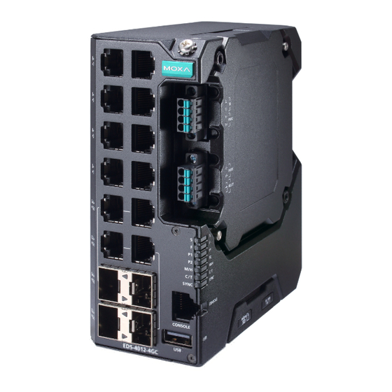
Communication Connections Each EDS-4012 Series switch has various types of communication ports: • RJ45 console port (RS-232 interface) • USB storage port (type A connector, currently disabled) • 10/100BaseT(X) Ethernet ports • 10/100/1000BaseT(X) or 100/1000BaseSFP combo ports • 100/1000BaseSFP slots •... - Page 11 RJ45 (8-pin) to RJ45 (8-pin) Straight-through Cable Wiring RJ45 (8-pin) to RJ45 (8-pin) Cross-over Cable Wiring 1000BaseT(X) Ethernet Port Connection 1000BaseT(X) data is transmitted on differential TRD+/- signal pairs over copper wires. MDI/MDI-X Port Pinouts Signal TRD(0)+ TRD(0)- TRD(1)+ TRD(2)+ TRD(2)- TRD(1)- TRD(3)+...
-
Page 12: Reset Button
LC-Port Pinouts LC-Port to LC-Port Cable Wiring ATTENTION This is a Class 1 Laser/LED product. To avoid causing serious damage to your eyes, do not stare directly into the Laser Beam. Reset Button There are two functions available on the Reset Button. One is to reset the Ethernet switch to factory default settings by pressing and holding the Reset button for 5 seconds. -
Page 13: Device Led Indicators
DIP Switch Settings DIP 1 DIP 2 DIP 3 DIP 4 DIP 5 ON: Enables the ON: Enables ON: Activates default “Ring this EDS as Enables the DIP switch 2, Coupling the Ring default 3, and 4 to (backup)” port Master. - Page 14 Color State Description 1. The relay contact has been triggered 2. The ingress rate limit has been exceeded and the port has entered shut down mode FAULT 3. Invalid Ring port connection When the system boots up and runs correctly or a user- configured event is not triggered.
- Page 15 Color State Description System Green + The switch is being Blinking Amber + discovered/located by the locator (Except (2 times/sec) function. PWR) System Green + Rotate The switch is importing/exporting Amber + On -> Off a file via ABC-02-USB or SD card (Except Sequentially (currently disabled)
-
Page 16: Specifications
Color State Description When the port is active and links 10M/ at 10Mbps. 100M Blinking When the port’s data is being Copper Amber (4 times/sec) transmitted at 10Mbps. bottom When the port is inactive or link down. When the port is active and links 10M/ at 1000Mbps. - Page 17 Power Boost (-LVB model): 62 W @ 12 VDC, 150 W @ 24 VDC (120 W for -T model), 180 W @ 48 PoE Output Voltage 55 VDC PoE Output Power 15.4 W for the 802.3af standard, 30 W for the 802.3at standard, 36 W in high power mode, 60 W in 802.3bt standard PoE Output Current 350 mA for the 802.3af standard, 600 mA for the...
- Page 18 EDS-4012-8P-4GS-LVA(-T) models: Without PoE: 13.34 W With PoE: Max. 240 W for total PD power consumption @ 48 VDC input EDS-4012-8P-4GS-LVB(-T) models: Without PoE: 15.32 W With PoE: Max. 180 W for total PD power consumption @ 48 VDC input; Max.
- Page 19 Warranty 5 years ATTENTION This device complies with Part 15 of the FCC rules. Operation is subject to the following conditions: 1. This device may not cause harmful interference. 2. This device must accept any interference received including interference that may cause undesired operation.
Need help?
Do you have a question about the EtherDevice EDS-4012 Series and is the answer not in the manual?
Questions and answers