
Related Manuals for Moxa Technologies EtherDevice EDS-G500E Series


Summary of Contents for Moxa Technologies EtherDevice EDS-G500E Series
-
Page 1: Hardware Installation Guide
EDS-G500E Series Hardware Installation Guide Moxa EtherDevice™ Switch First Edition, July 2013 2013 Moxa Inc. All rights reserved. P/N: 1802005000020... -
Page 2: Package Checklist
Package Checklist The EDS-G500E is shipped with the following items. If any of these items are missing or damaged, please contact your customer service representative for assistance. • 1 EDS-G508E or EDS-G512E-4GSFP or EDS-G516E-4GSFP Ethernet switch • Hardware installation guide •... -
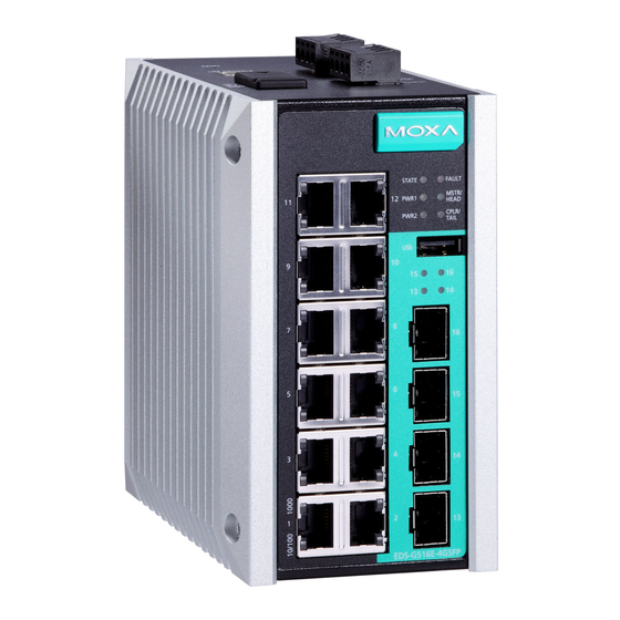
Page 3: Panel Views Of Eds-G500E Series
Panel Views of EDS-G500E Series Front Panel Front Panel 1. 1000BaseT(X) LED indicator 2. 10/100BaseT(X) LED indicator 3. 10/100/1000BaseT(X) ports EDS-G508E: 1 to 8 EDS-G512E-4GSFP: 1 to 8 EDS-G516E-4GSFP: 1 to 12 4. System status LED: • STATE LED indicator •... - Page 4 Top Panel Top Panel 1. Reset button 2. USB console port 3. DIP switches for Turbo Ring, Ring Master, and Ring Coupler 4. Grounding screw 5. 4-pin terminal block for digital input and power input 2 6. 4-pin terminal block for relay output and power input 1 Rear Panel Rear Panel...
-
Page 5: Mounting Dimensions
Mounting Dimensions Unit = mm (inch) - 5 -... -
Page 6: Din-Rail Mounting
DIN-Rail Mounting The metal DIN-rail kit is fixed to the back panel of the EDS-G500E series when you take it out of the box. Mount the EDS-G500E series on corrosion-free mounting rails that meet the EN 60715 standard. Installation STEP 1—Insert the upper lip of the DIN rail into the DIN-rail mounting kit. -
Page 7: Wall Mounting (Optional)
STEP 2—Mounting the EDS-G500E series on the wall requires 4 screws. Use the EDS-G500E series, with wall mount plates attached, as a guide to mark the correct locations of the 4 screws. The heads of the screws should be less than 6.0 mm in... -
Page 8: Grounding The Moxa Eds-G500E Series
Wiring the Relay Contact The EDS-G500E series has one set of relay output. This relay contact uses two contacts of the terminal block on the EDS-G500E’s top panel. Refer to the next section for detailed instructions on how to connect the wires to the terminal block connector, and how to attach the terminal block connector to the terminal block receptor. -
Page 9: Wiring The Redundant Power Inputs
EDS-G500E’s top panel. Wiring the Digital Inputs The EDS-G500E series has one set of digital input (DI). The DI consists of two contacts of the 4-pin terminal block connector on the EDS-G500E's top panel, which are used for the two DC inputs. The top and front views of one of the terminal block connectors are shown here. -
Page 10: Usb Console Connection
The EDS-G500E series has one USB console port (type B connector), located on the top panel. Use the USB cable (provided in the product package) to connect the EDS-G500E's console port to your PC's USB port and install the USB driver (available in the software CD) on the PC. You may then use a console terminal program, such as Moxa PComm Terminal Emulator, to access the EDS-G500E’s console configuration utility. -
Page 11: 1000Baset Ethernet Port Connection
TRD(3)+ TRD(3)- 100/1000BaseSFP (mini-GBIC) Fiber Port The Gigabit Ethernet ports on the EDS-G500E series are 100/1000BaseSFP Fiber ports, which require using the 100M or 1G mini-GBIC fiber transceivers to work properly. Moxa provides completed transceiver models for different distance requirement. -
Page 12: Turbo Ring Dip Switch Settings
When the ABC-02-USB is connected to the EDS-G500E Ethernet switch, the reset button allows quick configuration and backs up log files to the ABC-02-USB. Press the Reset button on top of the EDS-G500E, the Ethernet switch will start backing up current system configuration files and event logs to the ABC-02-USB. -
Page 13: Led Indicators
NOTE You must enable the Turbo Ring function first before using the DIP switch to activate the Master and Coupler functions. NOTE If you do not enable any of the EDS-G500E series switches to be the Ring Master, the Turbo Ring protocol will automatically choose the EDS-G500E series with the smallest MAC address range to be the Ring Master. - Page 14 Color Status Description 5. Invalid Ring port connection. Power is being supplied to the main module’s power input PWR1. PWR1 Amber Power is not being supplied to the main module’s power input PWR1. Power is being supplied to the main module’s power input PWR2.
-
Page 15: Specifications
Color Status Description SFP port’s 100 Mbps link is active. 100M Amber Blinking Data is being transmitted at 100 Mbps. (SFP) SFP port’s 100 Mbps link is inactive. SFP port’s 1000 Mbps link is active. 1000M Green Blinking Data is being transmitted at 1000 Mbps. (SFP) SFP port’s 1000 Mbps link is inactive. -
Page 16: Environmental Limits
Dimension 79.2 x 135 x 137 mm (3.1 x 5.3 x 5.4 in) Installation DIN-rail mounting, wall mounting (with optional kit) Environmental Limits Operating -10 to 60°C (14 to 140°F) for standard models Temperature -40 to 75°C (-40 to 167°F) for -T models Storage -40 to 85°C (-40 to 185°F) Temperature...
Need help?
Do you have a question about the EtherDevice EDS-G500E Series and is the answer not in the manual?
Questions and answers