
Related Manuals for Moxa Technologies EtherDevice EDS-4009 Series


Summary of Contents for Moxa Technologies EtherDevice EDS-4009 Series
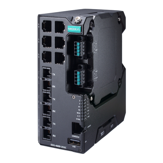
- Page 1 EDS-4009 Series Quick Installation Guide Moxa EtherDevice™ Switch Version 1.0, March 2022 Technical Support Contact Information www.moxa.com/support 2022 Moxa Inc. All rights reserved. P/N: 1802040090010 *1802040090010*...
-
Page 2: Package Checklist
Package Checklist The EDS-4009 Series industrial DIN-rail EtherDevice Switch (EDS) is shipped with the following items. If any of these items are missing or damaged, please contact your customer service representative for assistance. • 1 EDS-4009 Ethernet switch • Quick installation guide (printed) •... -
Page 3: Mounting Dimensions
Bottom Panel View 1. microSD card slot (currently disabled) 2. Reset button 3. DIP switches for Turbo Ring, Ring Master, and Ring Coupler Mounting Dimensions EDS-4009-3MSC(-T)/EDS-4009-3SSC(-T) Models - 3 -... -
Page 4: Din Rail Mounting
EDS-4009-3MST(-T) Models DIN-rail Mounting The DIN-rail mounting kit is fixed to the back panel of the EDS device when you take it out of the box. Mount the EDS device on corrosion- free mounting rails that meet the EN 60715 standard. Installation STEP 1—Insert the upper lip of the DIN rail into the DIN-rail... -
Page 5: Wall Mounting (Optional)
Removal STEP 1—Pull down the latch on the mounting kit with a screwdriver. STEP 2 & 3—Slightly pull the EDS device forward and lift up to remove it from the DIN rail. NOTE Our DIN rail kit now utilizes a quick release mechanism to make it easier for users to remove the DIN rail from the EDS device. -
Page 6: Wiring Requirements
NOTE Do not screw the screws in all the way—leave about 2 mm to allow room for sliding the wall mount panel between the wall and the screws. STEP 3—Once the screws are fixed to the wall, insert the four screw heads through the wide parts of the keyhole- shaped apertures, and then slide the EDS device... - Page 7 Be sure to read and follow these important points below: • Use separate paths to route wiring for power and devices. If power wiring and device wiring paths must cross, make sure the wires are perpendicular at the intersection point. NOTE Do not run signal or communications wiring and power wiring through the same wire conduit.
-
Page 8: Wiring The Relay Contact
In order to tighten the wire properly, ① use a small flathead NOTE We suggest the length of the pin type cable terminal is 8 mm. the terminal block connector before and during ② inserting the screwdriver to press the push-in button beside each terminal of wire. -
Page 9: Wiring The Redundant Power Inputs
Wiring the Redundant Power Inputs The EDS device includes both high-voltage and low-voltage products. For the low-voltage (LV models) products, there are two power inputs for redundancy; for the high-voltage (HV models) products, there is only one power input. Both use terminal block connectors on the right side panel of the product. -
Page 10: Communication Connections
STEP 1: Insert the negative (ground)/positive DI wires into the ┴/I terminals, respectively. STEP 2: To keep the DI wires from pulling loose, use a small flat-blade screwdriver to tighten the wire-clamp button on the front of the terminal block connector. STEP 3: Insert the plastic terminal block connector prongs into the terminal block receptor, which is... -
Page 11: 10/100Baset(X) Ethernet Port Connection
RJ45 Console Port Pinouts Description – USB Connection NOTE The USB function is currently reserved and may be required in the future. It should be noted that this port cannot be used for charging any devices. 10/100BaseT(X) Ethernet Port Connection The 10/100BaseT(X) ports located on the front panel of the switch are used to connect to Ethernet-enabled devices. -
Page 12: 100Basefx Ethernet Port Connection
RJ45 (8-pin) to RJ45 (8-pin) Cross-Over Cable Wiring 100BaseFx Ethernet Port Connection The concept behind the SC/ST port and cable is quite straightforward. Suppose you are connecting devices I and II. As opposed to electrical signals, optical signals do not require a circuit in order to transmit data. Consequently, one of the optical lines is used to transmit data from device I to device II, and the other optical line is used transmit data from device II to device I, for full-duplex transmission. -
Page 13: Reset Button
Reset Button There are two functions available on the Reset Button. One is to reset the Ethernet switch to factory default settings by pressing and holding the Reset button for 5 seconds. Use a pointed object, such as a straightened paper clip or toothpick, to depress the Reset button. This will cause the STATE LED to blink once a second. -
Page 14: Device Led Indicators
NOTE You must enable the Turbo Ring (DIP switch 5) first before using the DIP switch to activate the Master and Coupler functions. NOTE If you do not enable any of the EDS switches to be the Ring Master, the Turbo Ring protocol will automatically choose the EDS switch with the smallest MAC address range to be the Ring Master. - Page 15 Color State Description When the switch is Master/Head/Root of Turbo Ring/Turbo Chain/Fast RSTP. 1. The switch has become the Master of Turbo Ring after Turbo Ring has gone down 2. The switch is set as Head of Turbo Chain and Turbo Chain has gone down MSTR/ Blinking...
-
Page 16: Specifications
Color State Description When the port is active and links at 10M/ 10Mbps. 100M Blinking When the port’s data is being Copper Amber (4 times/sec) transmitted at 10Mbps. bottom When the port is inactive or link down. When the port’s data is being transmitted at 100Mbps. - Page 17 Power EDS-4009-3MSC-LV(-T) models: 9.51 W Consumption EDS-4009-3MSC-HV(-T) models: 12.14 W EDS-4009-3MST-LV(-T) models: 9.51 W EDS-4009-3MST-HV(-T) models: 12.17 W EDS-4009-3SSC-LV(-T) models: 9.51 W EDS-4009-3SSC-HV(-T) models: 12.34 W Inrush Current Max. 0.58 A @ 48 VDC (0.1 – 1 ms) (Applied to - LV models) Overload Current Supported...
- Page 18 Warranty 5 years ATTENTION This device complies with Part 15 of the FCC rules. Operation is subject to the following conditions: 1. This device may not cause harmful interference. 2. This device must accept any interference received including interference that may cause undesired operation. - 18 -...
Need help?
Do you have a question about the EtherDevice EDS-4009 Series and is the answer not in the manual?
Questions and answers