Table of Contents
Advertisement
Quick Links
Advertisement
Table of Contents

Subscribe to Our Youtube Channel
Related Manuals for Moxa Technologies EDS-4012 Series


Summary of Contents for Moxa Technologies EDS-4012 Series
- Page 1 ED S- 4 0 1 2 Se r ie s Quick I nst a lla t ion Guide M ox a Et he r D e vice ™ Sw it ch Ve r sion 1 .0 , M a r ch 2 0 2 2 Te chnica l Suppor t Con t a ct I nfor m a t ion w w w .m ox a .
-
Page 2: Package Checklist
Pa ck a ge Che ck list The EDS- 4012 Series indust rial DI N- rail Et herDevice Sw it ch ( EDS) is shipped w it h t he follow ing it em s. I f any of t hese it em s are m issing or dam aged, please cont act y our cust om er service represent at ive for assist ance. - Page 3 Grounding connect or screw 13. Sm art PoE LED indicat or of PoE port s Bot t om Pa ne l Vie w m icroSD card slot ( current ly disabled) Reset but t on DI P sw it ches for Turbo Ring, Ring Mast er, and Ring Coupler M oun t ing D im e n sion s...
- Page 4 D I N - r a il M ount ing The DI N- rail m ount ing k it is fixed t o t he back panel of t he EDS device w hen you t ake it out of t he box. Mount t he EDS device on corrosion- free m ount ing rails t hat m eet t he EN 60715 st andard.
-
Page 5: Wall Mounting (Optional)
W a ll M ount ing ( Opt iona l) For som e applicat ions, y ou w ill find it convenient t o m ount t he Moxa EDS device on a w all, as show n in t he follow ing illust rat ions: STEP 1 —Rem ove t he DI N- rail at t achm ent plat e fr om t he rear panel of t he EDS device, as... - Page 6 W ir ing Re quir e m e nt s ATTEN TI ON Sa fe t y Fir st ! Ext ernal m et al part s are hot . Take t he necessar y precaut ions if you are required t o handle t he device. ATTEN TI ON I n order t o ensure reliable operat ions, please m ake sure t he operat ing t em perat ure of t he environm ent does not exceed t he...
-
Page 7: W Ir Ing T He Re La Y Cont A Ct
Gr oun ding t he M ox a ED S Se r ie s Grounding and w ire r out ing help lim it t he effect s of noise due t o elect rom agnet ic int erference ( EMI ) . Run t he ground connect ion from t he ground screw t o t he grounding surface prior t o connect ing devices. - Page 8 Re la y: The t w o cont act s of t he 4- pin t erm inal block connect or are used t o det ect user- configured event s. The t w o w ires at t ached t o t he fault cont act s for m an open cir cuit w hen a user- configured event is t riggered or t here is no pow er supply t o t he sw it ch.
- Page 9 W ir ing t he D igit a l I nput s The EDS device has one set of digit al input ( DI ) . The DI consist s of t w o cont act s of t he 4- pin t erm inal block connect or on t he EDS's right - side panel.
-
Page 10: Communication Connections
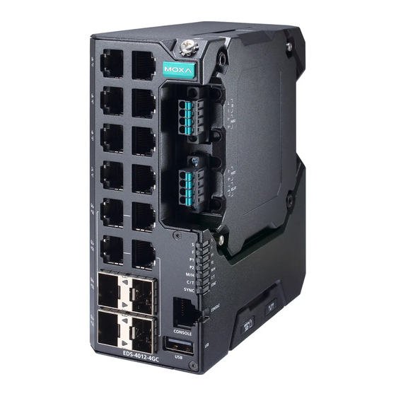
Com m unica t ion Conne ct ions Each EDS- 4012 Series sw it ch has various t y pes of com m unicat ion port s: • RJ45 console port ( RS- 232 int erface) • USB st orage port ( t ype A connect or, current ly disabled) •... - Page 11 RJ4 5 ( 8 - pin) t o RJ4 5 ( 8 - pin) St r a ight - t hr oug h Ca ble W ir ing RJ4 5 ( 8 - pin) t o RJ4 5 ( 8 - pin) Cr oss- ove r Ca ble W ir ing 1 0 0 0 Ba se T( X) Et h e r n et Por t Conn e ct ion 1000BaseT( X) dat a is t ransm it t ed on different ial TRD+ / - signal pair s over copper w ires.
-
Page 12: Tur Bo Ring D I P Sw It Ch Se T T Ings
LC- Por t Pinout s LC- Por t t o LC- Por t Ca ble W ir in g ATTEN TI ON This is a Class 1 Laser/ LED product . To av oid causing serious dam age t o y our eyes, do not st are direct ly int o t he Laser Beam . Re se t But t on There are t w o funct ions available on t he Reset But t on. - Page 13 D I P Sw it ch Se t t ings D I P 1 D I P 2 D I P 3 D I P 4 D I P 5 ON : Enables t he ON : Enables ON : ON : Act ivat es default “...
- Page 14 Color St a t e D e scr ipt ion The relay cont act has been t riggered The ingress rat e lim it has been exceeded and t he port has ent ered shut dow n m ode FAULT Re d I nvalid Ring port connect ion When t he syst em boot s up and...
- Page 15 Color St a t e D e scr ipt ion Syst e m Gr e e n + The sw it ch is being Blink ing Am be r + discovered/ locat ed by t he locat or ( Ex ce pt ( 2 t im e s/ se c) Re d funct ion.
-
Page 16: Specifications
Color St a t e D e scr ipt ion When t he port is act ive and link s 1 0 M / at 10Mbps. 1 0 0 M Blink ing When t he port ’s dat a is being Coppe r Am be r ( 4 t im e s/ se c) - Page 17 Pow er Boost ( - LVB m odel) : 62 W @ 12 VDC, 150 W @ 24 VDC ( 120 W for - T m odel) , 180 W @ 48 PoE Out put Volt age 55 VDC PoE Out put Pow er 15.4 W for t he 802.3af st andard, 30 W for t he 802.3at st andard, 36 W in high pow er m ode, 60 W in 802.3bt st andard...
- Page 18 EDS- 4012- 8P- 4GS- LVA( - T) m odels: Wit hout PoE: 13.34 W Wit h PoE: Max. 240 W for t ot al PD pow er consum pt ion @ 48 VDC input EDS- 4012- 8P- 4GS- LVB( - T) m odels: Wit hout PoE: 15.32 W Wit h PoE: Max.
- Page 19 Warrant y 5 years ATTEN TI ON This device com plies w it h Part 15 of t he FCC rules. Operat ion is subj ect t o t he follow ing condit ions: This device m ay not cause harm ful int erference. This device m ust accept any int erference received including int erference t hat m ay cause undesired operat ion.
Need help?
Do you have a question about the EDS-4012 Series and is the answer not in the manual?
Questions and answers